

About Radio Frequency Electronics Group
The Radio Frequency Electronics (RF) Group of IUAC is an Accelerator Support Group, which is responsible for the development, operation, and maintenance of various RF systems that are essential for the particle accelerators. The group plays a vital role in operating the Beam Pulsing System of the Pelletron accelerator during the pulsed beam runs. In addition, the RF Group is actively engaged in the design and development of new RF instrumentation and system upgrades to meet evolving research requirements and enhancing the manpower capbilities. These contributions are critical for sustaining reliable accelerator operations and enabling advanced experiments for the user community. The RF Group also manages a wide range of high-power RF amplifiers, microwave sources, and RF control electronics used across IUAC’s major accelerator facilities, including the Pelletron, High Current Injector (HCI), Superconducting Linac (SC-LINAC), Free Electron Laser (Delhi Light Source), and the Low Energy Ion Beam accelerator. The group is involved in the design, development, operation, repair, and periodic preventive maintenance of these systems to maximize uptime, improve performance, and enhance in-house technological development at IUAC. The RF power sources under its care cover a broad frequency range (4 MHz to 17.9 GHz) and power levels ranging from a few hundred watts to several tens of megawatts, incorporating both air-cooled and water-cooled amplifier types. In addition to technical responsibilities, the group also contributes to human resource development by training newly joined scientist trainees, apprentice trainees, and other technical staff, thereby strengthening the skilled manpower base at IUAC.
The primary activities include-
- Maintenance and Operation of Pelletron Beam Pulsing System
- Maintenance of RF Amplifiers installed at various facilities at IUAC
- Maintenance of LLRF electronics installed at various facilities at IUAC
- Development of high-power RF amplifiers and low-power control electronics
- Development of Nuclear Instrumentation modules
RF Amplifiers
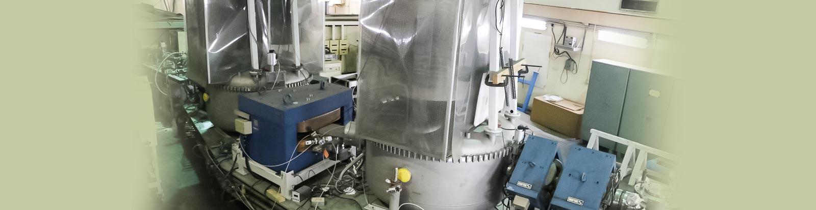
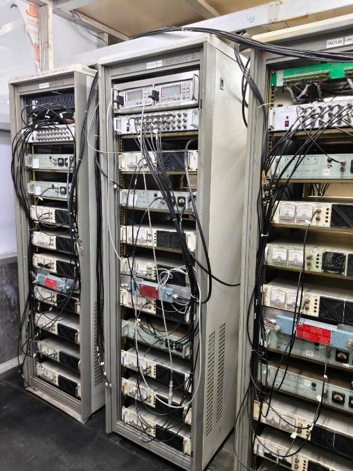
At the Inter-University Accelerator Centre (IUAC), RF amplifiers play a crucial role in driving the accelerating structures (RF cavities) by providing the required radio-frequency power for generation of RF fields to effect the beam acceleration. These amplifiers are especially designed to deliver high power at precise frequencies, ensuring efficient acceleration of charged particle beams in both linear accelerators and superconducting LINAC modules. The amplifiers are integrated with control and monitoring systems that maintain amplitude and phase stability, which are essential for minimizing beam energy spread and losses. Over the years, IUAC has developed expertise in designing, testing, and operating RF amplifiers ranging from low-power solid state units used for diagnostics to high-power vacuum tube–based amplifiers required for the main accelerating cavities. Continuous upgradation and rigorous testing of these amplifiers help in improving reliability, efficiency, and compatibility with evolving accelerator technologies, thereby supporting a wide range of nuclear physics experiments and user programs. The installed capacity of RF amplifiers and RF sources at IUAC range from 4 MHz to 17.9 GHz with RF power ranging from tens of hundreds of Watts in Pelletron to hundreds of Watts in SC-LINAC to tens of hundreds of kilowatts in HCI to megawatts in FEL. Below is a combined picture of installed amplifiers in various beamlines. Details of each facility is given in the following sections.

RF Amplifiers of Pelletron Beam Pulsing System
The RF amplifiers for the beam pulsing system of Pelletron consists for the following:
50 W, 4 MHz Chopper RF Amplifier
120 W, broadband RF Amplifier for Multi-Harmonic Buncher
The details of the design and characteristics are discussed below:
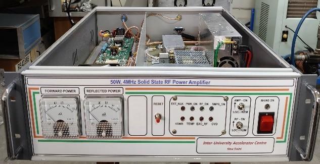
50 W, 4 MHz Solid State RF Power Amplifier
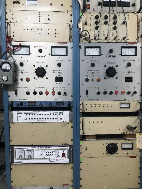
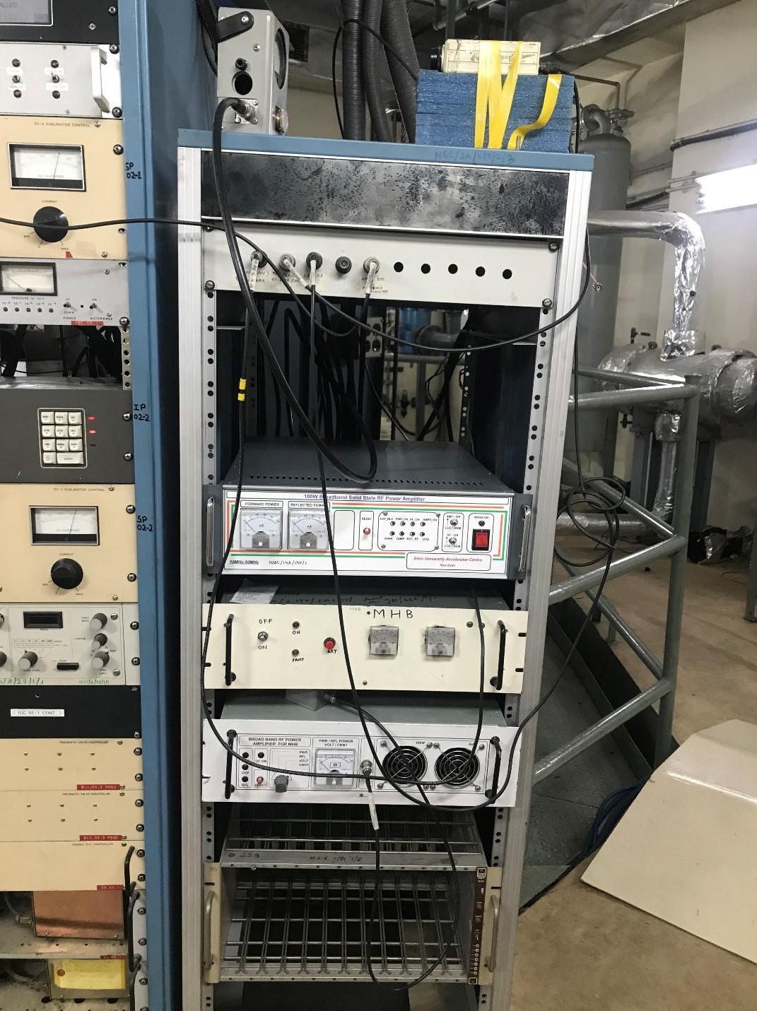
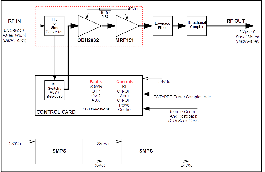
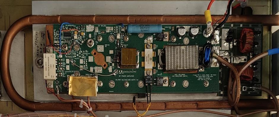
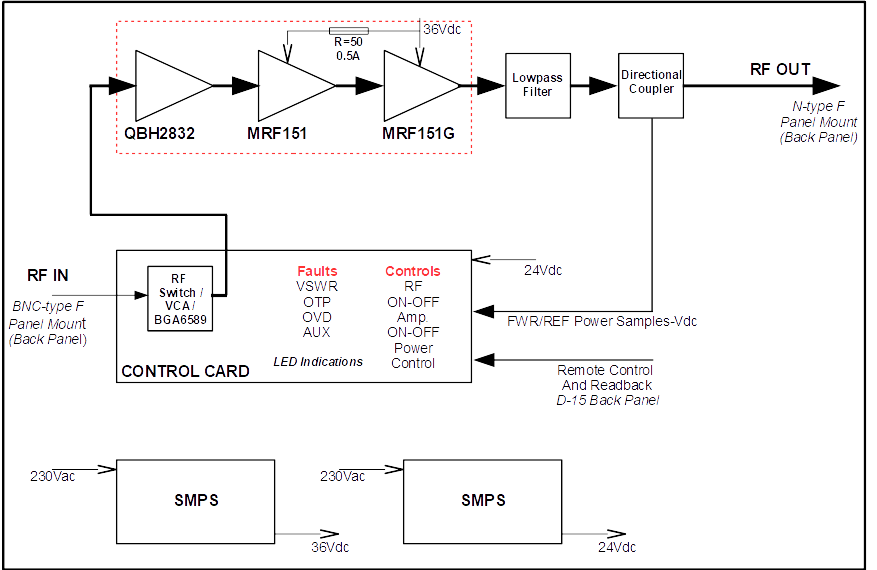
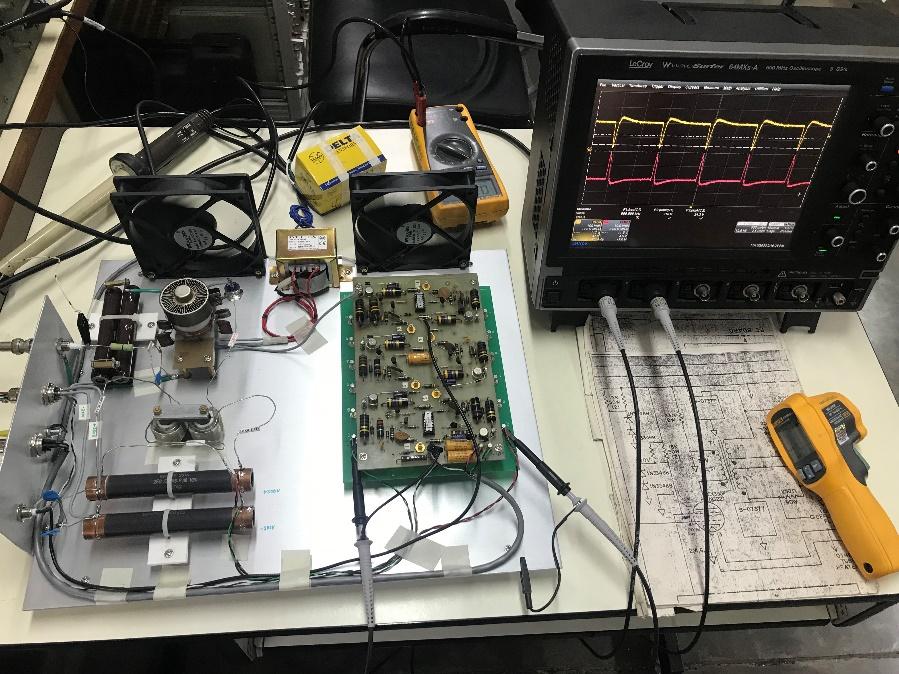
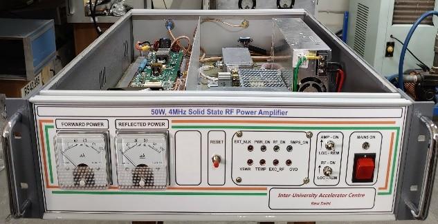
A 50 W at 4 MHz solid state RF power amplifier has been developed to power chopper plates of Pelletron Accelerator. A chopper is an electromagnetic device which makes use of RF power to sweep a portion of DC or continuous ion beam to generate pulses of ions. Earlier the chopper was powered by tube based commercial amplifier. As tubes are getting obsolete nowadays, also it involves high voltage, to overcome such problems the solid state RF power amplifier has been developed. The amplifier’s gain is built across three stage cascaded pre-driver, driver and power amplifier sections. The output power can be varied from 0 to 50W by changing control voltage from 0 to 10Vdc. Its subsystems are RF switch, Voltage Control Attenuator (VCA), a compact SMPS unit, control board, lowpass filter and a directional coupler. The MMIC BGA6589 as a pre-amplifier, QBH2832 as a driver and single ended MRF151 is used as a power amplifier. The RF MOSFETs MRF151 is operating at 40Vdc with gate biasing of 5Vdc regulated by LM723 versatile regulator chip. Amplifier control circuit is operating at +24Vdc. The power devices are mounted on copper heat spreader and in turn mounted on water cooled aluminum heat sink for high thermal stability and reliability. The power monitoring is possible with directional coupler and front panel analog power meters. The amplifier is enclosed in a 3U - 19” rack mountable standard aluminum cabinet.
Specifications
| Output Power | 50W(CW) |
|---|---|
| Input Power | +3dBm max. |
| Frequency Range | 1MHz – 6MHz |
| Gain Flatness | ±0.5dB |
| Impedance | 50Ω |
| Power Gain | 47dB |
| Mode of Operation | Class-A |
| Efficiency | 15% |
| Operating Voltage | +40Vdc |
| VSWR | 1:2 |
| Harmonics | Better than 45dB down(2nd)Better than 65dB down (3rd) |
| Protections | Over temperature at 60°C, over drive at +5dB, VSWR at 1:2 |
| DC Power | +40V/8A, +24Vdc/0.6A (Control Card) |
| AC Power | 230Vac/5A |
| Power Monitor | Analog meters for forward/reflected power measurement |
| Input/output connectors | BNC-Female / N-type Female |
| Cooling | Water cooled, min water flow 6 lpm, temp. 22̊C |
| Cabinet | 3Ux19”x440mm (HxWxD) |
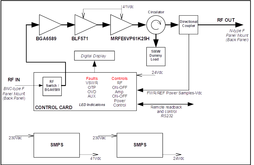
The block diagram and the amplifier pallet and finished product are shown below.
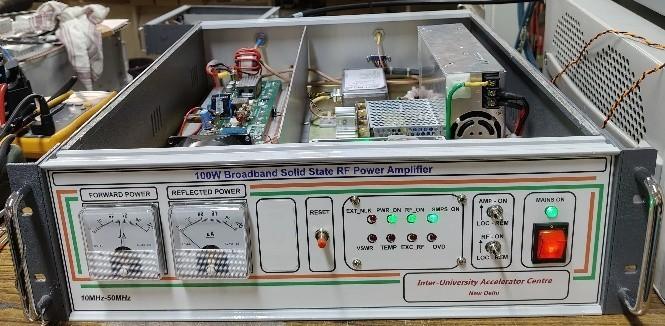
120 W, broadband Solid State RF Power Amplifier
A broadband solid state RF power amplifier is capable of delivering 120 Watts of power (CW) in frequency range of 10MHz – 50MHz (+/-1.5 dB) has been successfully developed with state of the art RF components for general purpose application. It is being used with Multi Harmonic Buncher (MHB) of Pelletron Accelerator at IUAC. The amplifier gain is built across three stage cascaded pre-amplifier, driver and power amplifier sections. Its subsystems are RF switch, a compact SMPS unit, control board and a directional coupler. The CATV block QBH-2832 is used as a pre-amplifier, RF MOSFETs MRF151 and MRF151G are used as driver and power amplifier respectively. The RF MOSFETs are operated at 36V dc with gate biasing of 5V regulated by LM723, a versatile regulator chip. Amplifier control circuit is operated at +24Vdc. The power devices are mounted on copper heat spreader and in turn mounted on water cooled aluminium heat sink for high thermal stability and reliability. The power monitoring is possible with directional coupler and front panel power meter. The amplifier is enclosed in a 3U - 19” rack mountable standard aluminium cabinet.
Specifications
| Output Power | 120W(CW) |
|---|---|
| Input Power | +3dBm max. |
| Frequency Range | 10MHz – 50MHz (-3dB BW) peaking at 26 MHz |
| Phase shift | ±5° max. |
| Gain Flatness | ±0.5dB |
| Power Gain | ~65 dB ( 15dB internal attn. ) |
| Mode of Operation | Class-A |
| Efficiency ( DC to RF) | 22% |
| Operating Voltage | +36Vdc |
| VSWR | 1:2 |
| Harmonics | -37dBc ( 2nd ), -14dB (3rd) |
| Protections | Over temperature at 60°C, over drive at +5dB, VSWR at 1:2 |
| DC Power | +36V/13A, +24Vdc/0.6A (Control Card) |
| AC Power | 230Vac/5A |
| Power Monitor | Analog meters for forward/reflected power measurement |
| Input/output connectors | BNC-Female / N-type Female |
| Cooling | Water cooled, min water flow 6 lpm, temp. 22̊C |
| Cabinet | 3Ux19”x440mm (HxWxD) |
The block diagram and the amplifier pallet and finished product are shown below.
RF Amplifiers of Superconducting Linac (SC-LINAC)
The superconducting Linear Accelerator (SC-LINAC) acts as the energy booster for the tandem Pelletron accelerator and in future for HCI as well. The LINAC beam line consists of a total of 27 quarter-wave resonators (QWR) which are Niobium based superconducting RF cavities. These QWRs are house in 5 different cryostats. Each cavity requires a 400 W RF high power RF amplifier operating at 97 MHz. Initially, some of these VHF amplifiers were made in collaboration with Bharat Electronics Limited while rest of the amplifiers were indigenously developed at IUAC. Below is the field deployment of various RF amplifiers in the LINAC beamline.
As part of the technological upgrade and to phase out the BEL made stock of RF power amplifiers, the RF group has recently re-designed the amplifier for the LINAC cavities.
400W, 97MHz Solid State VHF RF Power Amplifier
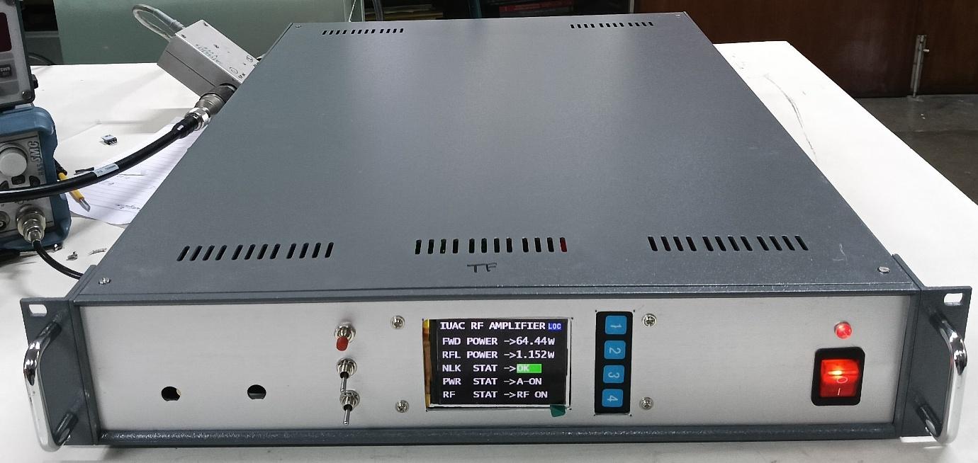
A 400W, 97MHz (CW) solid-state RF power amplifier has been developed to power the Superconducting LINAC cavities. The amplifier gain is built across three stage cascaded pre-amplifier, driver and power amplifier sections. Its subsystems are RF switch, a compact SMPS unit, control board and a directional coupler. The BGA6589 MMIC is used as a pre-amplifier, LDMOS BLF571 and MRE6VP61K25H are used as driver and power amplifier respectively. The amplifier includes various crucial protections against high VSWR, over temperature and input over drive. The amplifier is also provided with digital control and display for various parameters and RS232 interface for remote control and monitoring. All power modules are thermally managed using a water-cooled aluminium heat sink. The amplifier is housed in a 2U, 19-inch rack-mountable aluminium enclosure.
Specifications
| Output Power | 400W(CW) |
|---|---|
| Input Power | +3dBm max. |
| Frequency Range | 92MHz – 111MHz (-3dB BW) |
| Phase shift | ±7° max. |
| Gain Flatness | ±0.5dB |
| Power Gain | 56 dB |
| Mode of Operation | Class-AB |
| Efficiency ( DC to RF) | 50% |
| Operating Voltage | +41Vdc |
| VSWR | 1:∞ |
| Harmonics | -66dBc (2nd) , -55dBc (3rd) |
| Protections | Over temperature at 60°C, over drive at +5dB, VSWR at 1:∞ |
| DC Power | +41V /19A, +24Vdc /0.6A (Control Card) |
| AC Power | 230Vac/5A |
| Power Monitoring and control | Digital display and RS232 control and monitoring |
| Input/output connectors | BNC-Female / N-type Female |
| Cooling | Water cooled, min water flow 6 lpm, temp. 22̊C |
| Cabinet | 2Ux19”x600mm (HxWxD) |
RF Amplifiers for High Current Injector (HCI)
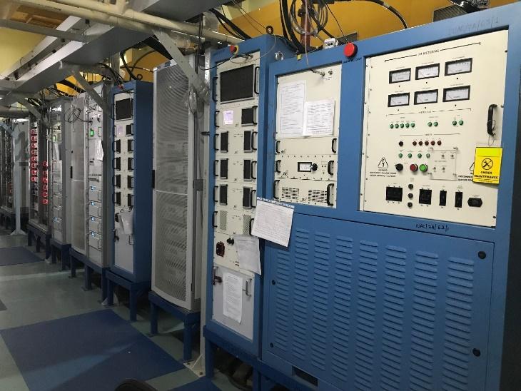
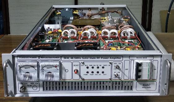
The high power RF infrastructure installed at the High Current Injector of IUAC consists of various RF cavities used for ion beam bunching and acceleration. Starting from the HTS-ECR based ion source which is excited by a klystron based microwave generator (1.7kW, 18GHz) which is operating in Ku-band of microwave regime or alternatively through a TWT amplifier operating in the same frequency regime, the ion beam can be bunched using a Multi-Harmonic Buncher(MHB) structure similar to IUAC Pelletron accelerator. A 100 W (10MHz -50MHz) broadband solid state-RF power amplifier is developed indigenously and deployed to enable the bunching mechanism. It is followed by a Radio Frequency Quadrupole cavity which fed by a tetrode based (Y567B) 120 kW, high power RF amplifier operating at 48.5 MHz. This amplifier is a commercial one of the M/s QEI-RF Inc., USA make. The RFQ is followed by a Spiral Buncher(SB) cavity which is fed with an indigenously developed 3kW, 48.5 MHz RF power amplifier. Ion beam from the spiral buncher enters a series of Drift Tube LINACs marked as DTL #1 to DTL #6 which are all 97 MHz RF cavities responsible for increasing the beam energy. All the DTL cavities are powered by commercial high power RF amplifiers which are either M/s DB Science, Italy make or M/s QEI-RF Inc., USA make. DTL #1 amplifier is rated for 6kW RF power, DTL #2 and 3 amplifiers are rated for 20 kW RF power each, DTL #4 and 5 amplifiers are rated for 28 kW amplifier RF power each and DTL #6 amplifier is rated for 30 kW RF power. All the amplifiers from DTL #1 to DTL #5, are solid-state amplifiers whereas the DTL #6 is a triode based amplifier. After DTLs, two more sets of spiral bunchers are available marked as SB #2 and 3 which are provide by a similar indigenously developed 3kW, 48.5 MHz solid- state RF power amplifiers. Below is the picture of installed high-power RF infrastructure in the main HCI beamline. In addition to the RF amplifiers, the group also work in close collaboration with the water systems group to ensure the correct flow rate of Low Conductivity Water which is of utmost importance for the smooth operation of various tube based amplifiers.
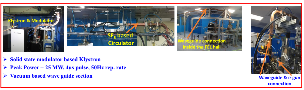
High Power RF System for Free Electron Laser (FEL-DLS)
The high-power RF system of FEL facility is entirely different from all the existing facilities at IUAC. It mainly consists of a Toshiba make S-band (2860 MHz), 25 MW Klystron as an RF power amplifier. The mode of operation is pulsed with a very low duty cycle of ~0.004% (maximum 4 microsecond pulse ON time at a maximum 50 Hz repetition rate). So, the pulsed low power RF signal generated by the LLRF is first amplified upto 230 W using a solid-state, pulsed 700 W RF driver power amplifier of make M/s Microwave Amps. Ltd. The high RF power is fed to the klystron input cavity whose cathode is operated at 251 kW, 255 A pulsed DC generated by a state-of-the-art solid-state high-power klystron modulator of make M/s Scandinova Systems A.B. Output of the klystron is fed to a 2.6 cell, normal conducting RF photocathode gun cavity fabricated in collaboration with KEK Japan through an in-vacuum, WR284 based rectangular waveguide RF delivery system. Various waveguide components like E-bend, H-bend, Directional Couplers, RF windows etc. have been installed. Ion pumps of make M/s Gamma Vacuum provide a very high vacuum of the range 1x10⁻⁹ mbar. To protect the klystron with huge reflections coming from the load (cavity), an SF6 based 4-port circulator based RF Isolator has also been installed. Entire RF system is protected by a rugged Beckhoff PLC based fast interlock mechanism. The RF group is responsible and trained to maintain, and resolve all the problems that occur with RF Driver Amplifier, High Voltage Charging Capacitor Power Supplies, High Voltage IGBT Switches and other interlock units. Apart from the preventive maintenances (twice per year), RF group also undertakes monthly periodic maintenance of the RF high-power system and the chiller units installed at the facility. Below is the figure of high-power RF system of FEL.
Low-Level Radio Frequency (LLRF) Controls
Low-Level RF (LLRF) control systems at IUAC are essential for the stable and precise operation of its accelerator facilities. These systems regulate the amplitude and phase of RF fields in the resonating structures of the Pelletron beam pulsing system,Superconducting Linear Accelerators (SC-LINAC), High Current Injector (HCI), and the Free Electron Laser (FEL-DLS).
At IUAC, the LLRF systems are customized to the specific needs of different facilities. For the Pelletron beam pulsing system, the initial controls were developed in collaboration with Argonne National Laboratory, USA.In addition, the group has envisioned and embraced the contemporary and futuristic digital signal processing techniques.
- LLRF Controls of Pelletron Beam Pulsing System
- LLRF Controls of Superconducting Linac (SC-Linac)
- LLRF Controls for High Current Injector (HCI)
- LLRF Controls for Free Electron Laser (FEL-DLS)
- Developmental Activities
LLRF Controls of Pelletron Beam Pulsing System
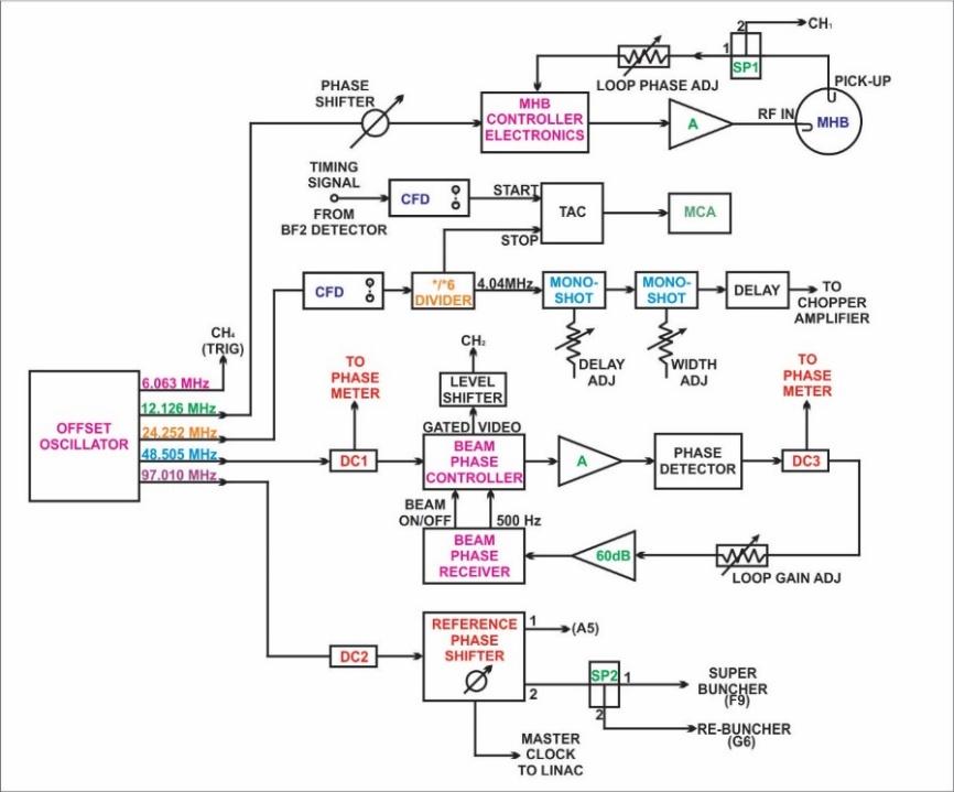
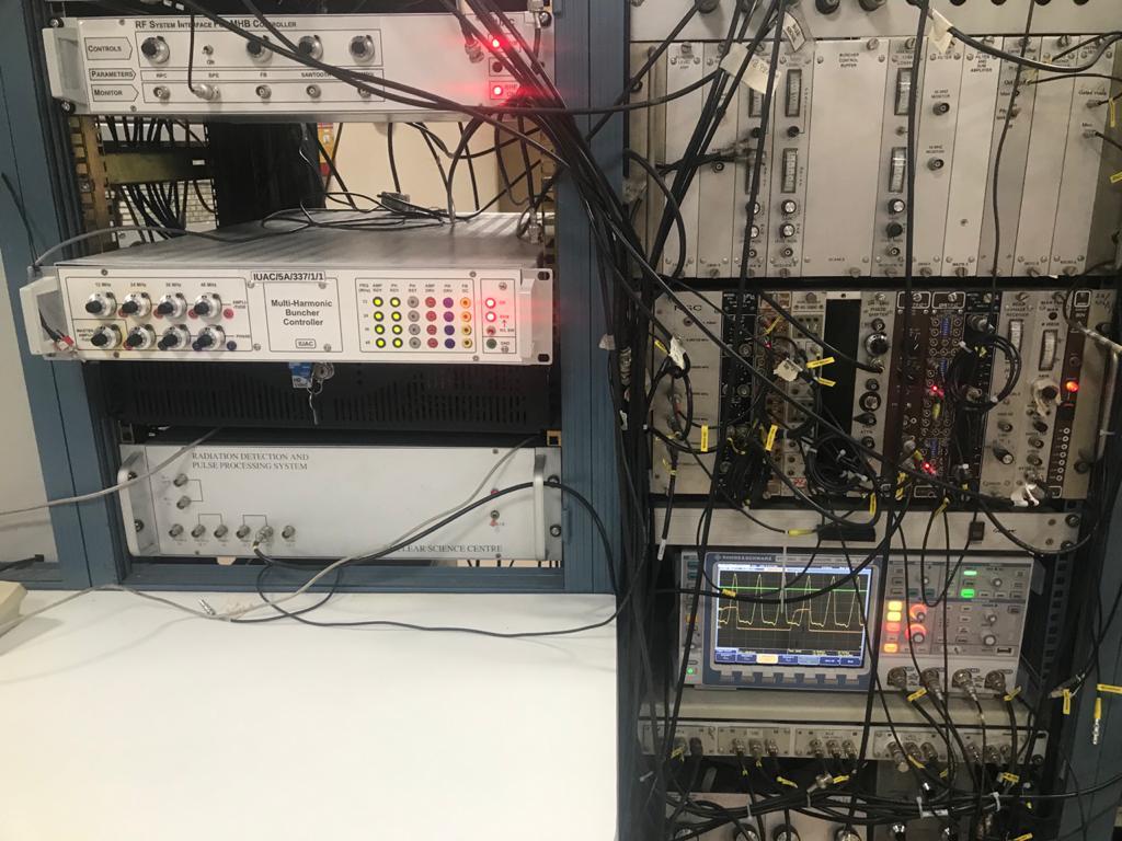
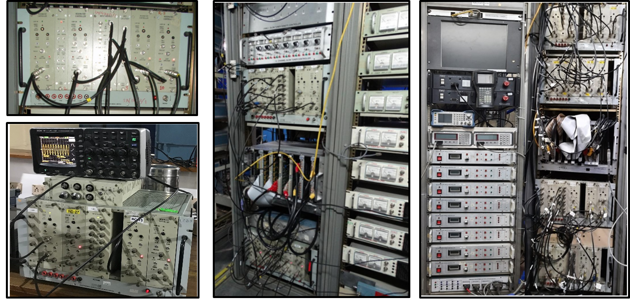
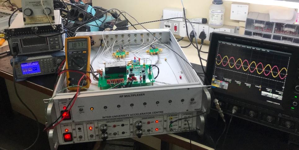
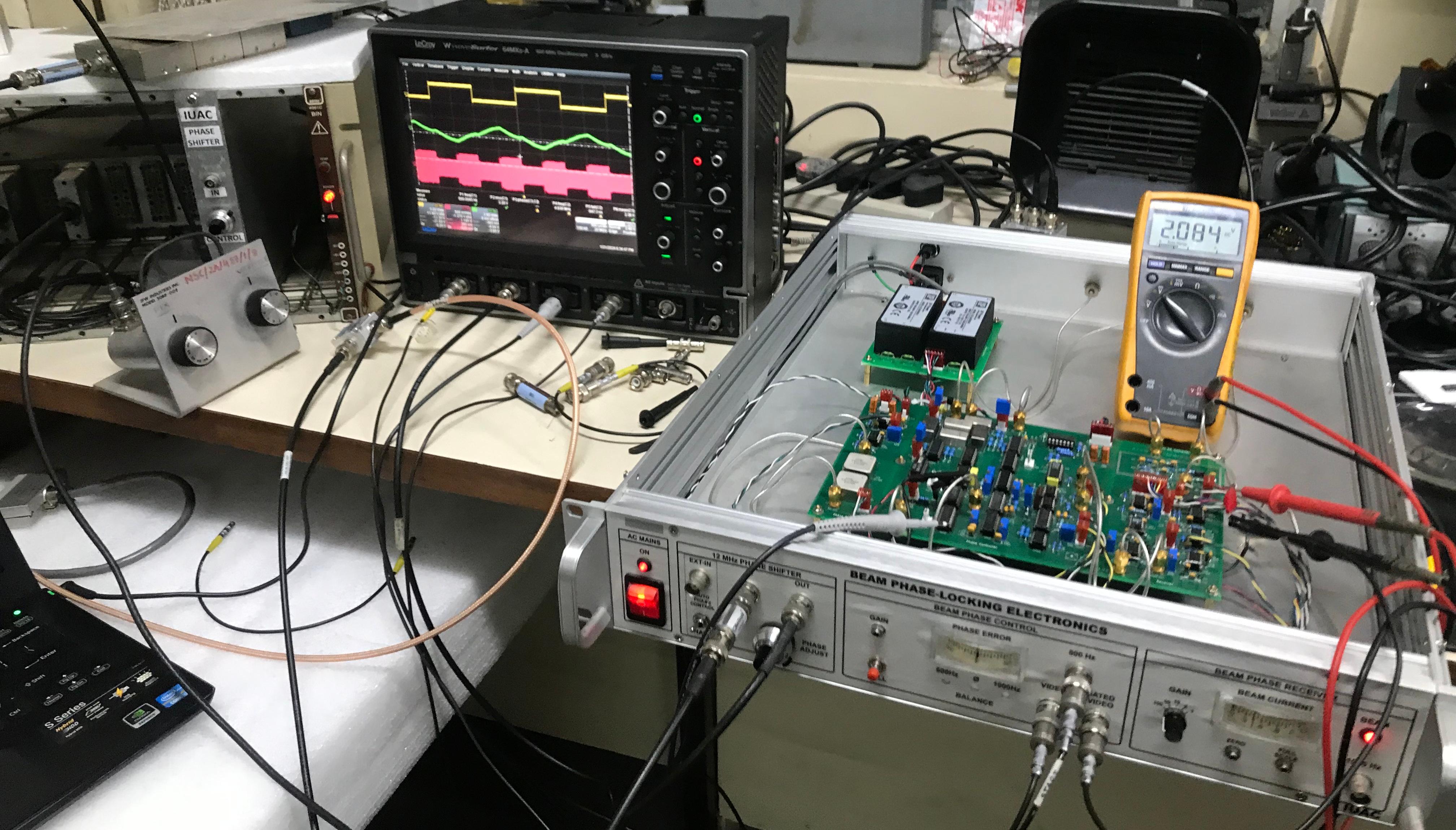
LLRF controls and other electronics of the Pelletron beam pulsing system are installed at various levels, including the main accelerator control room, the sixth floor, and the fifth floor in the pre-acceleration region of the accelerator tower. These include the master clock distribution system, the Multi-Harmonic Buncher (MHB) controller, and beam phase-locking electronics to synchronize the MHB with the phase variations of the beam, as well as timing electronics to measure the bunch width of the pulsed beam. The electronics required to control the entire beam pulsing system are installed on the fifth floor of the accelerator tower, in the form of NIM modules that were supplied along with the accelerator. The Traveling Wave Deflector (TWD) control electronics are mounted on the TWD itself on the sixth floor, while the associated power supplies and other electronics are installed on the fifth floor.
LLRF Controls of Superconducting-LINAC
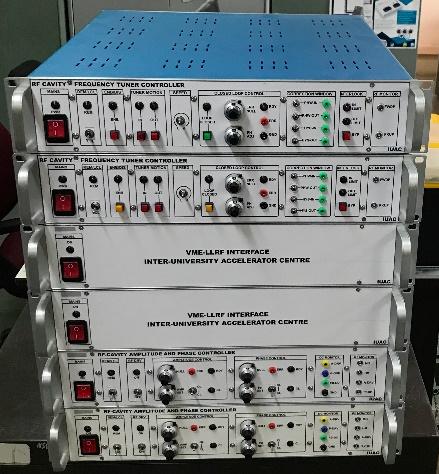
LLRF controls for the RF structures are broadly of two types based on the way resonance is stricken inside the cavities, viz: Generator Driven and Self Excited. The superconducting RF cavities of the LINAC facility (called the Quarter Wave Resonators (QWR)) are operated in Self-Excited mode which means that the role of LLRF electronics is to excite and sustain the resonance at the cavity’s natural frequency. While for acceleration purposes, such cavities are indeed phase locked to the Master Oscillator signal. Since the SC-LINAC serves as the energy booster to the Pelletron accelerator (and in future to HCI), the frequencies of operation have to be the integral multiple of the pulsed beam. So, the IUAC QWR cavities operate at 97 MHz while the pulsed beam at 12.125 MHz all derived from the the master clock distribution module located in the control room. The LLRF controls for QWRs consists of a reference splitter module, an input module and a resonator controller module as shown in the figure below. They are housed in a customized instrument bin which houses 4 nos. of Resonator Controller which are all supported by a reference splitter and an input module. Reference splitter, simply splits and provides master clock signal derived from the control room, while the input module conditions the incoming pick-up signal from the cavity and prepare it to be fed to the Resonator controller module in addition to generating a coupled signal. For the regulation of amplitude and phase, the Resonator Controller applies the complex phasor-based control using IQ modulation / demodulation apart from the proportional-integral based control on the amplitude and phase error signals.
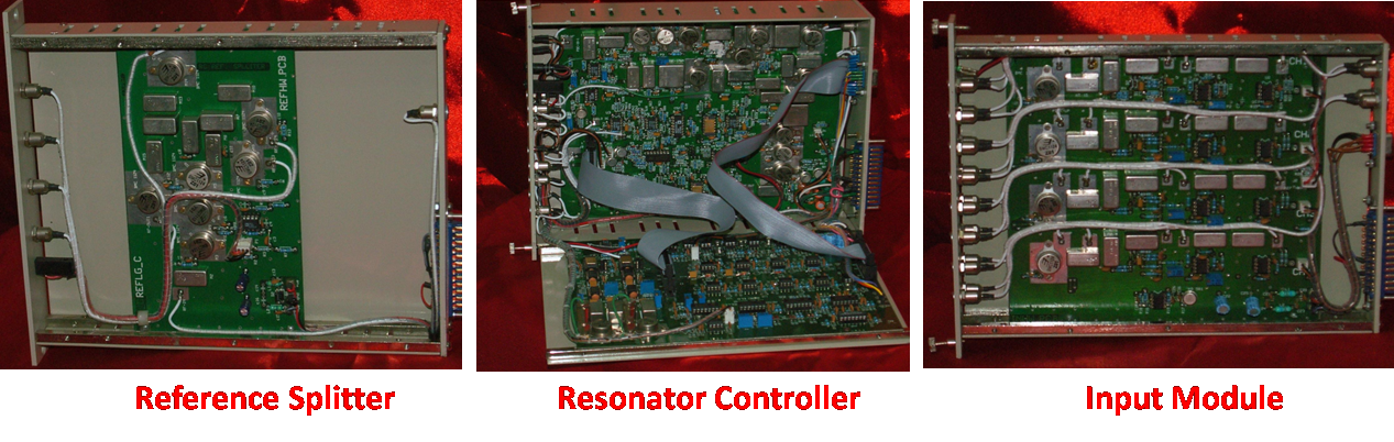
LINAC LLRF System Modules
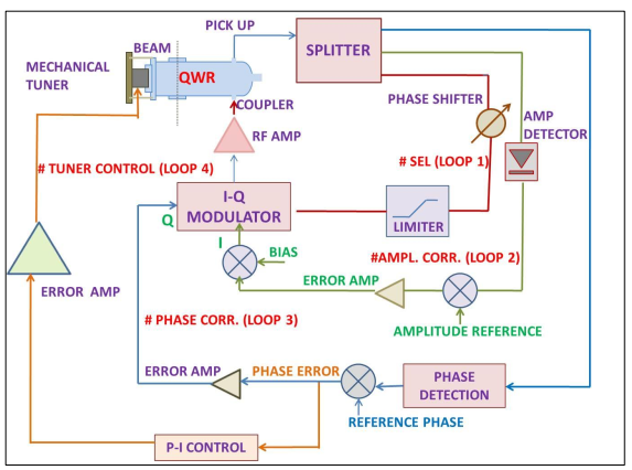
Block Diagram of the complex-phasor or IQ modulation based Self-Excited Loop control scheme is shown below. It includes three closed loop controls that provides Self-Excitation, Amplitude and Phase regulation respectively:
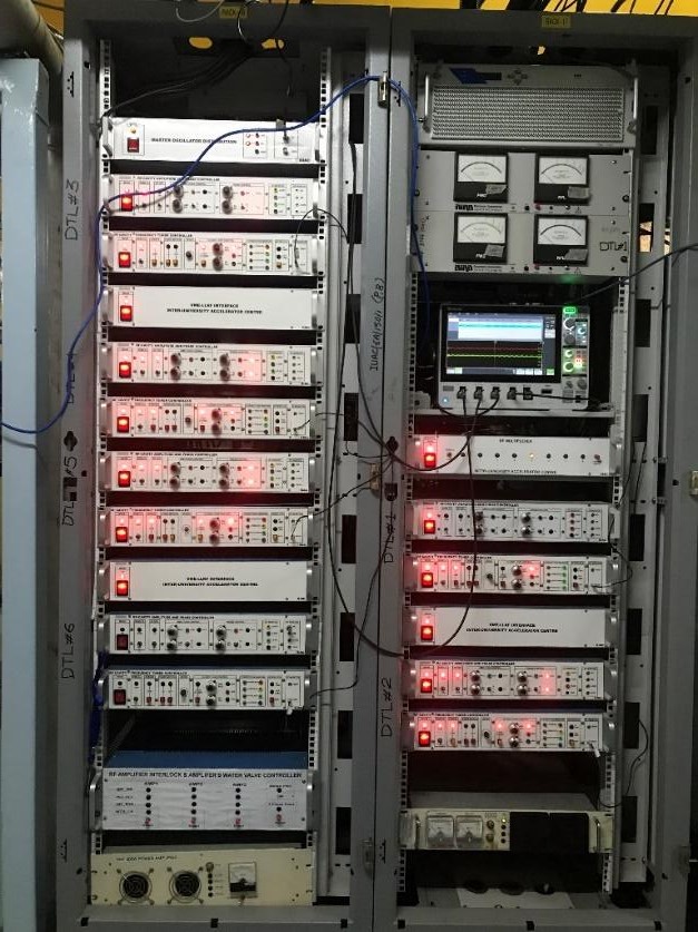
While the resonator controller provide fast corrections to the amplitude and phase distortions, each of the QWR is also aided with a pneumatic / piezoelectric actuator based frequency tuner control which is used to arrest the slow frequency variations like those arising from the microphonics. Piezoelectric actuator based frequency tuner control electronics are in-house developed by the BTS group and is currently maintained by the RF Group. The field deployment of the LLRF system is shown in the figure below.
LLRF Controls of High Current Injector (HCI)
The HCI employs fully in-house developed LLRF controls, demonstrating IUAC’s indigenous expertise. These LLRF systems operate on the Generator Driven principle wherein the cavity is made to follow the frequency of the external master oscillator signal. All the deployed systems in HCI are built using analog RF electronics that offer fast response times and operational flexibility. Various interlocks and protection mechanisms are integrated to safeguard the RF amplifiers and cavities from arcing, quenching, or excessive reflected power. With these controls, the HCI can deliver long-duration stable beams for user experiments, significantly enhancing accelerator performance and reliability with minimum downtime. In the initial phase, prototypes of the basic modules—namely amplitude and phase control systems and frequency tuner controls—were developed jointly by the BTS and LLRF groups. Subsequently, the RF group developed the remaining control modules required for the entire HCI facility, adding several features to enable complete remote operation. LLRF controls for the Multi-Harmonic Buncher (MHB), Radio Frequency Quadrupole (RFQ), three Spiral Bunchers, and six Drift Tube Linac (DTL) cavities have been installed and are operational. The frequency of operation is 12.125 MHz along with its two higher harmonics for the MHB, 48.5 MHz for the RFQ and Spiral Bunchers, and 97 MHz for the DTL cavities.
The HCI LLRF Controls include-
- Amplitude and Phase Controllers
- Frequency Tuner Controllers
- MHB Controller
- Master Clock Distribution Module
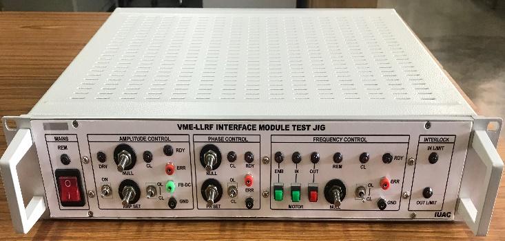
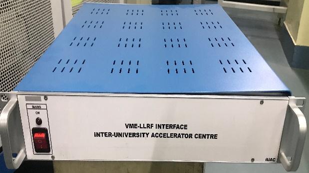
- LLRF-VME Interface modules
- RF Multiplexer based Parameters Monitor modules
LLRF Controls of Free Electron Laser (FEL-DLS)
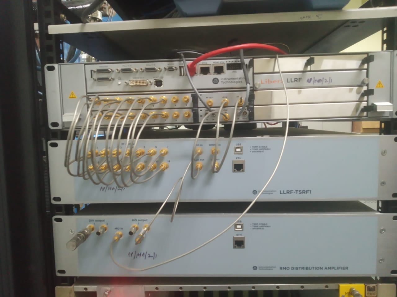
The FEL beamline consists of a room temperature, normal conducting 2.6 cell, 2860 MHz RF Gun cavity which hosts a Cu / Semiconductor photocathode. Upon interaction with a prebunched laser signal, this cavity yields an electron beam with energies upto 8 MeV. To accelerate the electron beam upto 8 MeV, the cavity makes use of very high pulsed RF power upto a maximum of 24 MW. A very low duty cycle of ~0.004 % mandates a very precise amplitude and phase control. A Libera make commercial Generator Driven based pulsed digital LLRF scheme has been deployed in this facility as shown in figure below. The main modules include a Reference Master Oscillator (which intakes a 2860 MHz RF signal and generates synchronized 130 MHz and 2860 MHz reference signals for laser-RF synchronization and LLRF), an Analog Front-End module (which down-converts signals from 2860 MHz to ~54 MHz IF signals), and a digital processor module (which intakes a trigger signal along with IF signals to provide required amplitude and phase closed loop control).
Apart from the LLRF controls, group has developed the entire remote control scheme, which is a heterogenous, distributed control system based on Experimental Physics and Industrial Control System (EPICS). All the beam line components like the high-power RF source, LLRF controls and the beam diagnostics have been deployed with EPICS control serves and client. Fast CMOS camera based pulsed beam viewer has also been deployed that provides the requisite beam statistics and also has the facility of background subtraction for dark current removal.
Developmental Activities
LLRF Electronics

Solid State RF Amplifiers for different facilities at IUAC

Nuclear Instrumentation Development at IUAC
The erstwhile Electronics laboratory of Inter University Accelerator Centre was actively involved in development of customized Nuclear Instrumentation for Nuclear Physics Experimental Applications as and when the experimenters have required due to non-availability of commercial systems. The group members have successfully developed various Nuclear Electronics modular units in a NIM standard modular form in various quantities to different experimental groups namely GDA (Gamma Detector Array), INGA (Indian National Gamma Array), NAND (National Array of Neutron Detectors), while maintaining the stringent specification requirements of the experimental groups. The group members have successfully shared the knowledge and skill gained to various other Institutions in order to duplicate these units as per their local needs.
Technical reports on Developed & produced General Purpose NIM modules
Gamma Ray Spectroscopy system with 1” & 2” PMTs
Dual Channel Ultra-Fast Discriminators
Multi-channel Time to Amplitude Converters (TAC)
Charge Sensitive Pre-amplifiers for General purpose Applications
Multi-channel Broadband & Charge sensitive Pre-Amplifiers for Proportional counters
Group’s Recent Publications:
Journal:
Ashish Sharma, et.al. “Compact embedded RF sawtooth waveform generator for particle accelerator applications”. AIP Advances 1 February 2025; 15 (2): 025228. Conference:
Parmanand Singh, et.al. “Development of 1.5kW, 48.5MHz solid state RF power amplifier”, proc. of DAE-BRNS National Conference on Development of RF components for Accelerators-2024, BARC Mumbai. Parmanand Singh, et al. “Development of 3kW, 48.5MHz solid state RF power amplifier ”, accepted in InPAC-2025, RRCAT Indore. Yaduvansh Mathur, et.al., A paper was presented “120kW, 48.5MHz vacuum tube RF power amplifier-operational experiences”, proc. of DAE-BRNS National Conference on Development of RF components for Accelerators-2024, BARC Mumbai. Ashish Sharma, et.al., “Design of a Generic Digital LLLRF Controller”, proc. of DAE-BRNS National Conference on Development of RF components for Accelerators-2024, BARC Mumbai. [Oral] Ashish Sharma, et.al., “Development of a Universal RF Controller for Accelerators at IUAC”, accepted in InPAC-2025, RRCAT Indore. V.V.V. Satyanarayana, et.al., “Development of Beam Phase-Locking Electronics for Pelletron Beam Pulsing System at IUAC”, accepted in InPAC-2025, RRCAT Indore.Group Members & Contact Details

Jr. Engineer-C

Engineer-D

Jr. Engineer-F

Jr. Engineer-F

Engineer-D

Engineer-G