

Cryogenics at IUAC
An heavy ion Rf-superconducting LINAC booster project for 15UD Pelletron accelerator is near to completion at Nuclear Science Centre. The acceleration would be performed with number of superconducting quarter wave resonators made of niobium which has a critical temperature 9.2K. Therefore the resonators have to be cooled below it's critical temperature to make operational, hence required liquid helium [4.2K] and associated cryogenic system.
The Superconducting Linac consists of one Buncher cryostat, three Linac cryostats, and a Rebuncher cryostat. Liquid Helium is produced by the LHe plant and transfers the liquid to the cryostats through the distribution line. The thermal radiation shields of the cryostats are cooled by the LN2 produced by the LN2 plant and transferred through the LN2 transfer line. The recirculation system of helium gas consists of an impure gas bag, recovery compressor, hi-pressure impure gas cylinders, helium purifier, and pure gas storage tanks. The entire cryogenic system is remotely monitored and controlled from the newly established cryo-control room.
The Primary Activities of Cryogenic Group
1. Operation and maintenance of the cryogenic facilities consist of
Liquid Nitrogen Refrigeration Plant
Liquid Nitrogen Plant of 5000 W refrigeration capacity at 77 K supplies LN2 to the LHe plant as pre coolant and it also cools the thermal shields of the cryostats and the distribution line. The Plant runs either in open-loop mode with 50 L/hr production capacity or in close loop mode with an enhanced production capacity of 110L/hr by using the cold return gas from the shield through the counter-flow heat exchanger. To have a sufficient buffer of LN2, there is an external tank of 5000L capacity in addition to the 5000L storage capacity of the plant. Another 20000L of the LN2 storage tank is yet to be installed in the yea 2004. All these storage tanks are integrated with the cryostats by vacuum jacketed and super-insulated transfer lines of 140m length.
Liquid Helium Refrigeration Plant
Helium Refrigeration Plant of 600W refrigeration capacity at 4.2K is based on the modified Claude Cycle. Its main components are two screw compressors of 28gm/sec throughput each, an LN2 Heat exchanger, two reciprocating expansion engines operating at 60K and 20K respectively, and a JT valve. The liquefaction capacity is 150L/hr. The plant is integrated with the cryostats of superconducting Linac by the LHe distribution network.
Helium Recycling System and Helium Purifier
The Helium recycling system consists of three pure gas storage tanks of water capacity 140M3, two impure gas bags of total 100M3 capacity, two recovery compressors of throughput 20M3/hr each, and a helium purifier.
A PLC-controlled fully automatic Helium Purifier has been designed in-house and integrated with the helium recycling system. The purifier works on the principle of adsorption by charcoal at 78K. It can purify 180M3 helium gas with 1% air inlet impurity.
Photo Gallery


2. Development of Various types of Cryostats for Rf-superconducting Linac program. The Cryostats are categorized into two types.
Off Line Cryostat
Simple Test Cryostat ( STC)
Simple test cryostat has been indigenously developed to perform the off-line testing of the niobium resonators at 4.2K by measuring the quality (Qo) and the accelerating field (Ea). This is cylindrical in shape, the thermal shielding is provided by the annular LN2 Vessel with a copper jacket inside it. The top shield is cooled by the evaporated helium gas. The measured static heat load is 1.5 W at 4. K and 225W at 77K.
Beam -Line Cryostats
Buncher Cryostat (BC)
Buncher Cryostat is the 1st beamline cryostat of Rf-superconducting Linac. It houses a single Nb-resonator. The thermal shield is made of copper cooled by the gravity feeding of LN2 from the top LN2 vessel. The Measured static heat load at 4.2K is 3W and 90 W at 77K
Linac Cryostat-I
Linac Cryostat-I is the 1st accelerating module of the superconducting Linac. Two modules are yet to come. Each module houses eight Nb resonators and one solenoid magnet. The thermal radiation shield which maintains 95K, is cooled by the forced flow of LN2@2bar. Precooling of the resonators and the helium vessel ( approximate cold mass ~ 500Kg) is done by the LN2 flow @ 20L/hr which flows through the channel welded on the resonator body and the LHe vessel. The resonators are cooled by the gravity feeding of the LHe from the vessel integrated with the cryogenic distribution network. Typical cooldown time from 300K to 4.2K is 24 hr.
Rebuncher Cryostat(RBC)
Rebuncher Cryostat, houses two Nb-resonators, is the last cryostat in the Linac beamline. Two annularLN2 vessels provide the thermal shielding for the resonators. A new technique has been adopted in this cryostat, during the cool down stage the evaporated helium gas is forced to circulate through the precooling channel of the resonators and LHe vessel. once the resonator temperature comes to 10K, the evaporated gas directly goes out without circulation.
Photo Gallery


")


For all the cryostats, the beamline vacuum and the cryostat vacuum are common hence vacuum should be better than 10E-9 torr. To achieve this high vacuum to have a clean environment around resonators no MLI is used to reduce the static heat load of any of the cryostats
3. Development of Cryogenic Distribution line with valve boxes to supply Liquid Helium from liquefier to the cryostats
Cryogenic Distribution Network
The Cryogenic distribution network has been designed in-house for parallel feeding of liquid helium to all beamline cryostats by using four-valve boxes. Except for the field joint section, the entire distribution line of approximately 40m length is liquid nitrogen shielded, multilayer insulated, and enclosed in a vacuum jacket of 8" diameter. The measured average heat load is less than 1W/m out of which 60% is contributed by the valves vacuum brakes and the uninsulated portion of the line.
4. Development of Cryogenic Data Acquisition and Control System (CRYODACS)
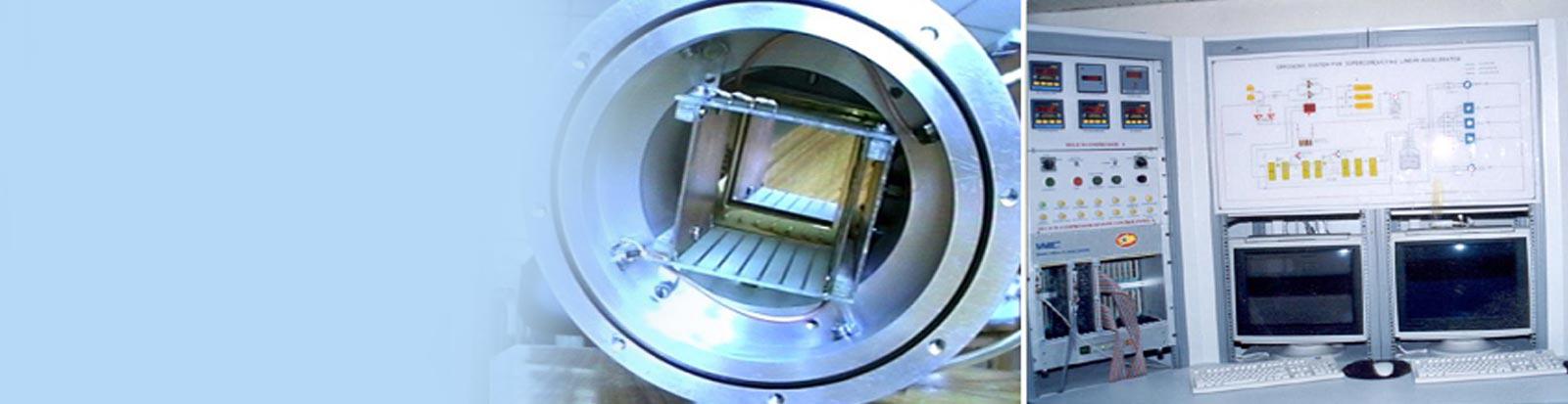
CRYODACS
All the cryogenic systems are partially automatized using a VME based cryogenic data acquisition and control system(CRYODACS). All the data from helium compressor helium liquefier, beamline cryostats, and cryogenic distribution lines are brought into the cryogenic control room through a 1000MBPS ethernet connectivity to minimize the cabling. The hardware architecture of CRYODACS is VME bus with VxWorks through WINDOWS2000 server host OS. Several clients under Windows operating system linked by NSC LAN.
Other Developments
- An arc-cell-based helium purity measurement system has been developed to measure ppm level impurity.
- A test set-up has been made to study the performance of the Multi-Layer Insulation (MLI).
- The thermal conductivity measurement set-up for the cryogenic material is under development.
Photo Gallery


5. Other Developments
- Development of Helium Purity measurement system using arc-cell.
- Experimental Test Set-up to study the performance of MLI.
- Thermal conductivity measurement set-up.
Group Members
-
Mr. T.S. Datta
-
Mr. Jacob Chacko
-
Mr.Anup Chowdhury
-
Mr.Soumen Kar
-
Mr.Joby Antony
-
Mr.Manoj Kumar
-
Mr.Suresh Babu
-
Mr.R.S.Meena
-
Mr.S.A.Krishnan