

DELHI LIGHT SOURCE(DLS)-A COMPACT THz FREE ELECTRON LASER FACILITY
1. Overview
Delhi Light Source (DLS), is a compact accelerator based light source to produce THz radiation based on the principle of Free Electron Laser. In DLS, the electromagnetic radiation with high peak intensity will be generated by micro-bunched electron beams. The concept of DLS stems from the fact that the coherent emission from the pre-bunched electron beams can be achieved immediately from the injection point of the compact undulator magnet. This is only possible if the bunch length of the electron microbunches is much shorter than one radiation wavelength (λL) with all the microbunches separated successively by one λL (this also helps to improve the bunching factor). If this condition is satisfied then inside the undulator, the radiation emitted from a given microbunch meet the electrons in the advanced micro-bunches. Thus the photons are added up in phases and the intensity of radiation is proportional to (Ne x Nm)2, where Ne is the no. of electrons in each micro-bunch and Nm is the number of micro-bunches varying from 1 to 16. This is commonly referred to as super-radiant undulator radiation.The pre-bunched electron beam will be produced by the laser micro-pulses striking the Cu or Cs2Te semiconductor photocathode. There will be provision to vary the separation of the laser micro-pulses and thus, the separation between the electron bunches can be also varied. If the separation of the electron micro-bunches is made to be equal to the required wavelength of the radiation emitted by the electron beam through the undulator magnet with its adjusted magnetic field then the photons emitted from the microbunch trains will be added up in phase and the intensity of the radiation will be maximised. ।

| पैरामीटर | मान |
|---|---|
| Frequency of Radiation | 0.18-3 THz |
| Electron Beam Energy | 4-8 MeV |
| Electron gun | 2.6 cell Photocathode based RF cavity, frequency 2860MHz, S band, π Mode |
| Types of Photocathode | Cu/ Cs2Te |
| Type of Laser System | Yb Doped Fiber Laser with multi-micro bunch structure with splitting mechanism |
| Temporal width of electron bunch (FWHM) | ~300fs |
| Energy spread | <1% |
| Emittance (RMS) | ~ 1-2mm-mrad |
| Charge per pulse | 6 pC |
| Peak Current | >20 Amp |
| Undulator Type/ legth/gap | Plannar/2m/48mm |
| Experimental station | Electron beam and THz |
2. Recent Development
The pre-bunched Free Electron Laser facility has been commissioned and presently produces electron beam for conducting experiments in Materials Science, Biology and Atomic physics. Last year, after final installation of the high-power RF source with Circulator, RF Conditioning of the RF gun could be performed up to 5 MW of RF power and production of electron beam up to 4.5 MeV was demonstrated and measured using Dipole magnet#1 and Integrated Current Transformer (ICT). This year, the beam line from Dipole magnet#1 has been extended up to the beam dump installed after Dipole magnet#2. Now the complete beam line is equipped with both the Dipole magnets of the 60 degree achromatic bends, Beam Position monitors, Beam viewers, ICTs, vacuum pumps etc. Two different experimental chambers are installed to perform experiments with the electron beam. The THz extraction chamber equipped with Ti-foil to reflect THz radiation at 45-degree angle is also installed post undulator section and efforts are being dedicated to detect THz radiation produced by the undulator using a pyroelectric detector. The development of fiber-based laser system for this facility in collaboration with KEK Japan is completed and the system has successfully produced electron beam at LUCX facility of KEK. The laser system has been transported to IUAC and has been installed at IUAC. It is expected that in the next few months the femtosecond electron beam from the electron gun will be produced and the same will be injected into the compact undulator for production of coherent THz radiation.

Electron beam for user experiments
During the last academic year, a nanosecond UV laser having wavelength (266 nm) was made to incident on the cathode to produce electrons from the copper photocathode and electron beam energy values at different accelerating fields of the electron gun along with the charges were measured.
| University | Experiments | Energy of the electron beam | Total beam time (hours) |
|---|---|---|---|
| Atomic Physics IUAC | Measuring ionization cross section with high energetic electron beam | 2 MeV | 40 |
| JNU | Effect of e-beam on activated carbon to enhance its removal property of heavy metal toxic elements in water | 2 MeV | 12 |
| St. Edmund's College, Shillong | Irradiation on Bakelite sample (for Nuclear detector) delivering accumulated dose by e-beam | 4 MeV, 5 MeV | 8 |
| Chaudhary Charan Singh | Low Energy Electron Beam affecting | 5 MeV | 24 |
| University, Meerut. | physiological and biochemical attributes of Garden Pea Plant in association with ZnO nanoparticles, Total 60 samples were irradiated | ||
| IIT Hyderabad | Sample type CVD grown 2D MoS2 on SiO2/Si (Thin film), sample size 5x5mm | 1 MeV | 48 |
1 FEL beam line
The first phase of the DLS facility at IUAC aims to produce both ultra-short electron beam bunches of energy 2 to 8 MeV and intense THz radiation in the frequency range of 0.18 to 3.0 THz. For this a compact beam line has been designed and installed inside a class-10000 clean room. Conceptual design of the beam line and detail about its components will be described in the following sections.
The Phase-I consists of two beam lines i.e. radiation beam line and electron beam line. Both the beam lines will have their own experimental stations inside the clean room (as shown in figure-1).

In the conceptual design, a detailed beam line components has been planned in a schematic diagram with their actual dimensions. for phase-I of the DLS project has been done. The detail schematic of the above said beam line is shown in figure-2.

During the last academic year, the Undulator Magnet along with its narrow vacuum chamber had been precisely aligned and the beam energy was measured by using the dipole magnet installed at the achromatic bend. In this academic year another dipole magnet along with magnetic quadrupole triplet and steering magnets were installed to complete the achromatic bending section of the electron beam line. The sixty degree (60) bending section of the second dipole magnet was aligned with the experimental chamber along with the quadrupole doublets and steering magnet for the delivery of electron beam to the experimental chambers to be dedicated for electron beam related experiments. The zero-degree line of the first dipole magnet was also aligned with an additional experimental chamber for atomic physics experiments. The BPM along with ICT are being installed in this beam line for tuning of the beam to the experimental chamber. The view of the installed beam line post undulator section along with design drawings of the entire beam line is shown in Figure 3.

Beam Optics Simulation
The beam optics simulation of DLS is done in two stages, firstly from PC gun to undulator exit to optimize for radiation output of the THz frequencies and secondly from undulator exit through an achromatic bend to guide the electron beam to electron experimental stations. For the first section ASTRA (A space charge tracking algorithm) and GPT (General particle tracer) softwares has been used for the simulations, whereas for the second stage GICOSY has been used in addition to GPT. After first order optimization from GICOSY, the GICOSY parameters was used for simulation in GPT. The GPT results for the complete beamline is shown for 4MeV beam in figure 1.

Figure 1: The results of GPT simulation for 4MeV beam showing the variation of beam transverse rms size with Z, from PC gun to electron experimental station. The transverse beam profile at Undulator exit and electron experimental station is also shown.
The simulation for DLS has been done by trying to optimize the Bunching factor(BF) of the bunch through the Undulator for a given frequency. This is achieved by maximizing sum of BF square inside the Undulator. The simulation results for 3 THz frequencies using 16micro-bunches is shown in figure2.


Figure: The top plot is of the beam rms size in X & Y along the beam line, the middle left plot shows the BF at 3.0THz through the undulator and the middle right plot BF spectrum at PC gun, Undulator entry, middle and exit locations. The bottom plot shows the bunch X-Z profile at PC gun, Undulator entry, middle and exit respectively
High Power RF system
The specification high power RF system for the Delhi Light Source project of IUAC is derived from the beam requirement of the system. The photoinjector cavity resonating at 2860 MHz (i.e. S-band) with a maximum gain of 8 MeV is required to accelerate the laser induced photo-electron beam to generate THz radiation in the frequency range of 3 THz. To produce such a gain, accelerating fields of the order of ~115 MV/m are required which translates to ~19 MW of RF power. The RF power source for the photoinjector cavity, with the above specification is based upon a 25 MW peak power klystron operating in pulsed mode for maximum 4 µs duration. The main components of High Power RF system are High Voltage Pulse Modulator, Solid State Driver Amplifier, S-band Klystron, RF Waveguide System and Ion Pumps. The system has been commissioned at IUAC and the solidworks drawing of whole assembly and actual site picture is shown in figure 1.

The specifications of the modulator are shown in the Table1.
| Parameter | Value | Unit |
|---|---|---|
| Klystron RF peak power | ≥ 25 | MW |
| Klystron average output | ≥ 5 | kW |
| Operating PRF range | 1-50 | Hz |
| Pulse length (flat top) | ≤ 4 | µs |
| Top flatness | ±0.3 | % |
| Rate of rise and fall | 311, 243 | kV/ µs |
| Pulse-to-pulse stability | 42 | ppm |
A 2.6 cell S-band copper cavity is being used as the RF gun to work as photoinjector cavity. It has been fabricated in collaboration with KEK, Japan, tested with low power RF. The cavity is under evacuation in the DLS beam line at present and has been aligned at its correct position. The high power RF system has been installed and commissioned based on final location of this cavity. The resonance frequency of the cavity is 2860 MHz and the measured Q-value is ~ 15200 with low power RF. The cavity and its electric field profile from Superfish and from the bead pull measurement are shown in figure 2.

During the last Academic year, after installation of the SF6 based Circulator, rigorous RF conditioning of the RF photo cathode gun was initiated in 247 mode and maximum RF field gradient of 65 MV/m (at 4 MW of RF Power) was generated inside the photo cathode gun. At higher field gradients, due to excessive electron discharge or arcs at the RF junctions, several anomalies occurred that caused high reflected power, which in turn affected the cavity or waveguide vacuum conditions and caused the system to trip In order to avoid such incidents and to reduce the frequency of system trips, a machine learning algorithm has been developed that can predict a sustainable and stable vacuum / pressure levels at different RF power levels and if the vacuum level ever tries to go out of control, then it can reduce or control the power level automatically to prevent the system from tripping. Currently this program is being deployed in the control scheme for uninterrupted RF conditioning of the photocathode Gun and the system is being conditioned for 10 MW of RF Forward power. The Energy of the produced electron beam was measured to be 6 MeV at 9 MW of RF Power. An EPICS GUI is also developed for monitoring and recording of various parameters during RF Cavity conditioning. Figure 3 shows the cavity conditioning at 5 MW with 4 microsecond of pulse duration.

Photocathode Deposition System
In the DLS facility which is under development at Inter University Accelerator Centre, New Delhi, initially, the electron beam will be generated from copper photocathode and subsequently from semiconductor photocathode like Cs2Te and other advanced photocathode materials. To deposit the thin film of photocathode material on metal substrate, a deposition system has been designed at IUAC and fabricated at Brookhaven National Laboratory (BNL),USA under joint collaboration. The system consists of four vacuum chambers which will be interconnected with vacuum manipulator with the option of isolating by gate valves (shown in figure 1). The system will have provision for cleaning of photocathode metal substrate (to be called subsequently as PC plug), deposition of photocathode film on the PC plug, storage of the PC plug without residual gas poisoning and insertion of the PC plug into the RF electron gun. The operating vacuum in all the chambers in the facility will be in the order of 10-11 mbar for ensuring minimum residual poisoning of photocathode thin film.

At present, the production of electron beam is being continued by striking the laser beam on the Cu photocathode. In order to improve the quality of the electron beam in terms of bunch width, emittance, energy spread, etc., semiconductor photocathode (Cs2Te) deposition system had been installed in last academic year. After installation of photocathode deposition system along with other accessories like vacuum elements, magnetic manipulators, source chambers etc., the evacuation was done and a leak rate of 5x10-12 mbar mbar had been achieved. Installation of source assembly has been completed and temperature calibration of cathode substrate is completed. The positioning of the Quartz Crystal Monitor (QCM) with respect to the substrate was optimized by measuring ~1/5th of film thickness measured by QCM compared to the deposition thickness on the substrate. A UV LED system was installed just outside the deposition chamber and the laser beam was aligned so that it would hit the substrate kept inside the deposition chamber to measure the quantum efficiency of the photo cathode during deposition.
Fiber Laser system
The laser system is one of the most crucial subsystem of the Delhi Light Source (DLS) facility for the production of THz. The concept of DLS stems from the fact that the coherent emission from the pre-bunched electron beams can be achieved immediately from the injection point of the compact undulator magnet. The pre-bunched electron beam will be produced by the laser micro-pulses striking the photocathode. A state-of-the-art Fiber Laser system to produce ultra-short laser pulses with energy ~1.5 Joule at UV (255 nm) with a pulse width of 500 femto-seconds was developed as a collaborative project between IUAC and High Energy Accelerator Research Organization (KEK), Japan. The development of the laser system is successfully completed and the production of electron beam is demonstrated by using the Fiber Laser system of IUAC.
, fiber stretcher, pre-pre- amplifier and pre-amplifier")


| Parameters | Values |
|---|---|
| Repetition Rate | 130 MHz (Tunable) |
| Oscillator power | 120mW (Max) |
| Long Term RMS stability | 0.5% |
| Multipulse and Burst rate | 5-10 MHz at 10 Hz inside 4 µs |
| Pulse width (FWHM) | ~300fs |
| Burst Energy (IR) | ~1mJ (1030nm) |
| Burst Energy (Green) | ~100µJ (515nm) |
| Burst energy (UV) Max | ~10 µJ (258nm) |
Undulator
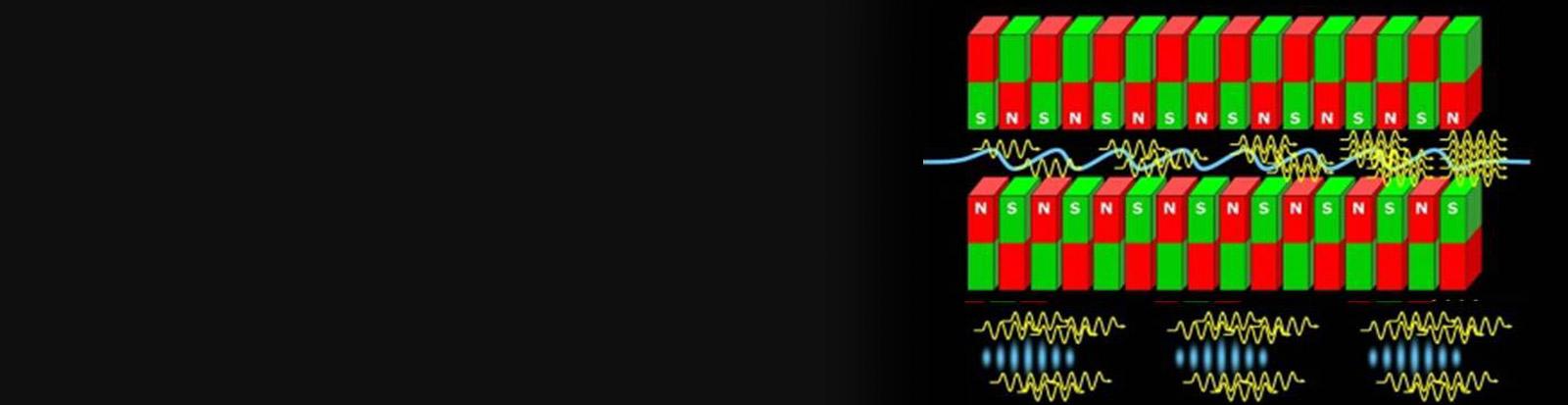
Undulator is a periodic arrangement of magnets in such a way that the particle passing along its axis experience a sinusoidally varying magnetic field (Fig. 1).

The relativistic electron beam will be injected into the undulator magnet and produce electromagnetic radiation. The wavelength λ of nth harmonic of radiation is given by the famous undulator equation,
λ = λu / (2nγ2) (1 + K2/2 + θ2γ2)
where λu is the undulator period, γ is the relativistic factor for electron, K= 0.0934*B[T]*λu [mm] is the undulator parameter, B is the on- axis peak magnetic field of undulator and θ is the angle at which the radiation is emitted (or the observation angle) with respect to z-axis.
The DLS is designed to produce the radiation wavelength in the range of 0.18 THz to 3 THzfrom electron beam of 4 MeV to 8 MeV. The undulator for this light source was received from HZB, Germany to use their spare undulator whose specifications closely match with the designed one. Few refurbishments were done at DESY,Germany to make it suitable for the installation at IUAC. Table 1 shows the specificationsof the undulator now being used.
| 1. | Undulator | U48 |
| 2. | Installation at | Delhi Light Source (DLS), New Delhi |
| 3. | Undulator technology | Pure Permanent Magnet (PPM) |
| 4. | Magnet material | NdFeB |
| 5. | Number of periods | 33 |
| 6. | Undulator period | 48 mm |
| 7. | Individual magnet dimensions | 70 mm(y-height) × 22 mm (z-width) x 12 mm (x-thickness) |
| 8. | Length of undulator | 1584 mm (only the magnet structure) Total length 2400 mm |
| 9. | Mechanical configuration | 90° rotated, main field in horizontal direction |
| 10. | Undulator gap: working range | 16 mm (minimum)- 45 mm (maximum) 140 mm (open gap) |
The undulator has been shifted from DESY and has been installed in the beam line. The alignment was done using the Taylor – Hobson Fudicial. Vaccum chamber inside the undulator has been aligned and connected to the beam line (Figure 2). Electron beam has been successfully transmitted through the undulator chamber with 80% of transmission efficiency. The short and long coil are also has been powered. The gap will be varied to get the different radiation wavelength of the generated THz. Field Integral and correction coil currentmeasurement data has been shown in figure 3.


THz Transport and Detection:
The terahertz radiation has to be captured just at the exit of the undulator to reduce its further loss and attenuation while propagating through the vacuum chamber. At the end of the undulator, an extraction chamber equipped with a Titanium foil is installed. The foil will reflect the THz radiation in perpendicular direction and allow the electron beam to pass through. The reflected THz radiation will be collected using a Teflon lens and parabolic mirrors, and then transported to the experimental stations with the help of mirrors and lenses. The schematic is shown in figure 1 to detect the THz using Michelson interferometer set up.

Table 1 shows the calculated THz power generated using the Lienard Wiechert formulation when the electron microbunches passes through the undulator.

Figure 2 shows the installed extraction chamber in the DLS beam line along with parabolic mirrosrs and pyroelectric detector set up to detect the generated THz.

Last Updated on: 01/08/2025
Free Electron Laser Photo Gallery


