Research Activities and Experimental Facilities
Material Science at LEIBF
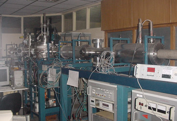
The ninety-degree beamline is used for material science experiments (including implantation, surface modification, sputtering, etc) in a dedicated chamber provided with a multiple sample holder that can be either heated (for high-temperature implantation, for example) or cooled to liquid nitrogen temperatures. In addition, online electrical conductivity measurements can be done.
Liquid Droplets
The experiments with 'liquid droplet clusters' is a novel area of research that is fascinating in its own right since microdroplets are macro clusters having bulk-like packing densities, and yet exhibit certain properties of large molecules/small clusters due to their spatial confinement. In other words, microdroplets combine the properties of size-confined molecular/cluster systems and the high-density targets. We have initiated radically new experiments to understand the interaction dynamics (charge transfer, ionization, and fragmentation) of droplets in their collisions with highly charged ions (HCI) of low energy (in the KeV-MeV range). These experiments are of interest not only from the fundamental point of view of understanding ion-droplet collisions but also from a technological point of view since they are expected to bring forth new advancements in techniques to produce highly-excited molecules/ions and pulsed x-ray sources.
The microdroplets (of low viscosity liquids under high pressure) are generated by uniform break up of a high-velocity microjet that emerges from a piezo crystal-driven microcapillary tube of 10 microns diameter. On applying a disturbance of wavelength /lambda = 2.pi.rj (rj is the radius of the jet) symmetric about the jet axis, the microjet breaks up into a train of uniformly-sized microdroplets, with the inter droplet spacing equal to the disturbance wavelength. The size of the droplets (in the air), as determined by Mie scattering, is 17 microns.
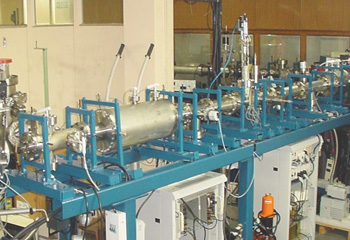
The infrastructure developed by us for such experiments constitutes a beamline (15 degrees) for transporting the highly-charged ions from the ECR source to the experimental chamber, and a UHV experimental chamber with a large number of ports for mounting various detectors like x-ray and particle detectors. The 15-degree beamline that is dedicated to such novel experiments has become operational of late. It consists of indigenously fabricated electrostatic quadrupoles (doublet and triplet) and electrostatic steerer. The photograph on the right shows the 15-degree beamline at LEIBF. The high voltage feed-throughs for the quadrupoles and steerers have been fabricated in-house.
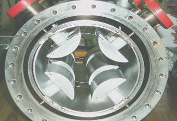
The photograph on the left shows an indigenously fabricated electrostatic quadrupole triplet. The commercially available beam diagnostic elements like the beam profile monitor (BPM) and the Faraday cup have been installed at suitable positions along the beamline. All the high voltage power supplies (for quadrupoles) are remotely controlled through the RS232 interface. A manually-operated double slit in the beamline allows for cropping the peripheral beam. The unique combination of the dipole magnet and the electrostatic quadrupole doublet, together with the electrostatic quadrupole triplet allows for obtaining an m/q selected and doubly focussed low energy highly charged ion beam with unit magnification at the center of the experimental chamber.
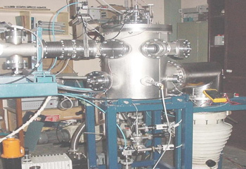
The UHV experimental chamber for HCI-droplet interaction studies is shown in the photograph on the left. It houses a cryopump system and a differential pumping system apart from the conventional high-capacity pumps (rotary-backed diffusion pump), for achieving and sustaining a high vacuum when the liquid droplets are introduced into it. A special arrangement for collecting the droplet train and pumping it out has also been made. The chamber has a number of ports around the interaction region so as to accommodate photon and particle detectors. A flexible bellow arrangement for mounting the piezo crystal-driven microcapillary tube allows for aligning the droplet train in a vacuum. The microdroplets interact with low-energy highly charged ion beams in crossed-beam geometry. Such interaction results in multiple ionization of the target droplets, leaving them in highly excited states, followed by fragmentation of the same. The dynamics of the collisional interaction can be understood by monitoring x-ray emissions and detecting the product ions formed in the Coulomb explosion of the droplet, by time-of-flight (TOF)spectrometry.
The ECR source
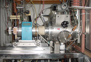
The Low Energy Ion Beam Facility (LEIBF) at the Inter-University Accelerator Centre provides multiply charged ion beams at a wide range of energies (a few keV to about a MeV) for experiments in Atomic, Molecular, and material sciences. The facility consists of an Electron Cyclotron Resonance ion source (Nanogan from Panteknik) installed on a high voltage deck. This kind of unique facility based on all permanent magnet (NdFeB) design for radial and axial confinement of plasma provides an excellent opportunity to research materials science, atomic physics, and surface physics. All the electronic control devices of the ECR source including the high-power UHF transmitter (10 GHz), are placed on a high voltage deck. These are controlled through optical fiber communication in multiplexed mode. Design and development of the high voltage platform, accelerating system and the beamlines with components thereof like electrostatic quadruple triplet lens, all-metal double slit, beam steerers, Faraday cups, all-metal pneumatic straight-through valve, UHV scattering chamber have been indigenously made.
The ECR ion source installed on the high voltage deck is shown in the figure. This facility is very useful for various exciting experimental research programs in materials science, e.g. ion beam induced epitaxial recrystallization, hetero- and nano-structure formations in semiconductors, modification of surface and near-surface properties of materials, rare earth doping of semiconductors, and interactions of highly charged ions with solid surfaces. Typical ion beams, range of charge states, energies, and beam currents are mentioned below:
| Type of ion | Range of charge states (q) | Range of energy (E) | Range of beam current (euA) |
|---|---|---|---|
| Oxygen (O) | 1+ to 6+ | 50keV to 0.9MeV | 0.1 to 100 |
| Argon (Ar) | 1+ to 10+ | 50keV to 1.5MeV | 0.1 to 15 |
| Xenon (Xe) | 1+ to 20+ | 50keV to 3.0MeV | 0.1 to 15 |
| Lead (Pb) | 1+ to 15+ | 50keV to 2.2MeV | 0.1 to 8 |
Beam Production Techniques
The ECR source can be used to produce a wide variety of beams. The following techniques are available:
- Gas inlet: This is the simplest and most robust way to produce ions. The element whose ions are required is injected into the ECR source in the form of a gas. This is straightforward for the noble gasses and elements like oxygen, nitrogen, hydrogen, etc.
- Micro-oven: For elements that cannot be obtained in gaseous form, a micro-oven is available. The oven is inserted into the plasma chamber and can be heated up to 1000 degrees C. Volatile compounds can therefore be loaded into the micro-oven and be used to produce ions.
- Sputtering: A mechanized arrangement to insert a long thin wire (1mm or 0.5mm thick) wire of any element may be introduced into the source plasma volume. The high-energy electrons can sputter out elements present in the wire, ionize them and produce the required beam.
- MIVOC: For metal ions, the technique of Metal Ions from Volatile Organic Compounds has been indigenously implemented. Organic compounds that have a metal atom, and are volatile are sealed into a stainless-steel chamber and then allowed to permeate the ECR source volume. This allows us to extract metal ion beams that are difficult to produce by other techniques.
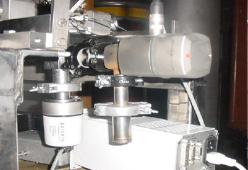
Photograph on right shows the indigenously developed MIVOC setup. The volatile compounds are placed in a quartz tube in the SS304 tube at bottom. The gas flow is controlled by the electronically operated valve at the top right. The vacuum gauge is at bottom left.
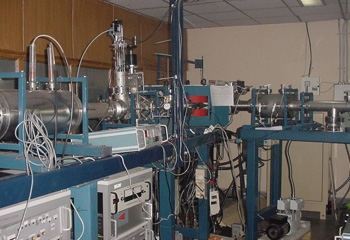
The ion beams extracted from the ECR source are charged and mass analyzed by a dipole magnet and injected into one of two available beamlines (one at ninety degrees and one at fifteen degrees). The figure shows the dipole magnet which switches the beam between the two experimental beamlines.


