

Inter-University Accelerator Centre
The 15UD Pelletron accelerator facility at IUAC has been operational since July 1991. It has completed 34 years of successful operation. Over the years since its installation, it has been providing ion beams to more than 400 users from India and abroad. The majority of the user communities are from universities in the country. The 15 UD Pelletron, Phase-1 area consists of five established beamlines for conducting experiments involving basic and applied research in nuclear physics, atomic physics, material science (MS-I), atomic mass spectrometry, radiation biology and other allied fields of Gamma Detector Array (GDA) & General Purpose Scattering Chamber (GPSC). The accelerator has been operational over a wide range of energies. To achieve further higher beam energies, the Pelletron accelerator serves as the injector to Super Conducting Linear Accelerator (LINAC), injecting energized particles that are subsequently boosted in energy. With this extended setup (or Phase-II experimental area), the established facilities are National Array of Neutron detectors (NAND), Materials science-II, INGA (Indian National Gamma Array )- HYRA (HYbrid Recoil mass Analyzer)and Atomic physics.
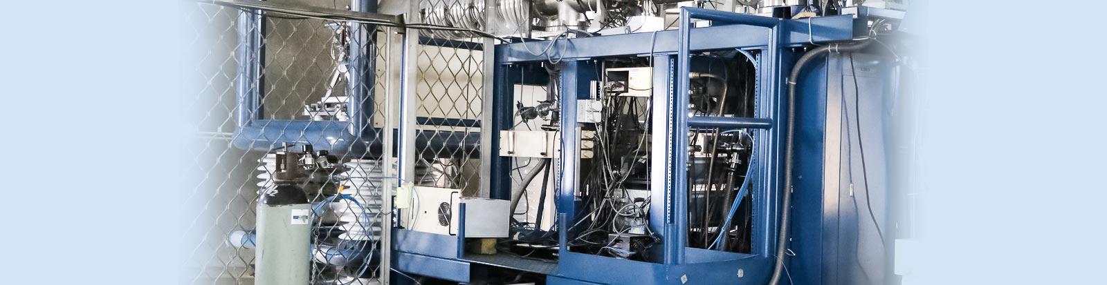
Pelletron Accelerator
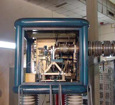
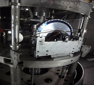
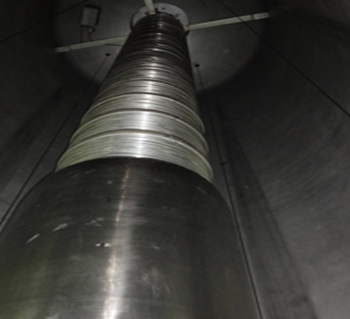
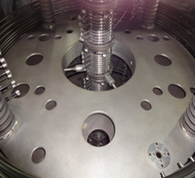
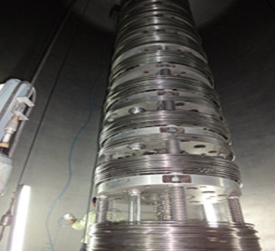
The 15 UD Pelletron, designed by NEC, USA, is a tandem electrostatic accelerator capable of delivering ion beams of nearly all stable nuclei, with energies reaching up to 200 MeV depending on the ion species. The ion source for this machine is Multi Cathode cesium sputter negative ion source (MC-SNICS). The negative ions are produced and pre-accelerated up to ~ 300keV energy in the ion source area. The desired ion beam is selected and also bent from the horizontal plane to the vertical plane using 1.2 Tesla Injector magnet. These ions are injected into the 15 UD pelletron for acceleration. The electrostatic accelerator is installed in vertical configuration inside a tank filled with high pressurized (~80 psi) SF6 insulating gas. The tandem accelerator has both ends at the ground potential with high -voltage terminal at the middle. The terminal is connected to the tank vertically through accelerating tubes. These tubes maintained a potential gradient from the tank top to the terminal as well as from the terminal to the tank bottom. Two metal stainless steel pellet charging chains are used for the generation of high voltage at the terminal using Vande Graaff generator principle. The terminal potential can be varied from +4 to +16 MV for the delivery of the beam according to the user’s experimental requirements.
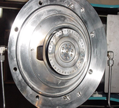
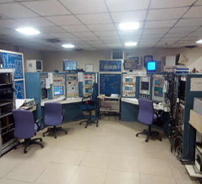
The acceleration is due to the electrostatic attraction between the negative ions and the high positive potential terminal. The terminal is equipped with a gas stripper differentially pumped by two turbo pumps and a foil stripper assembly. On reaching the terminal, negative ions pass through a stripper which strips off electrons, thereby converting them into highly charged positive ions. These ions are again accelerated through reducing potential from terminal to the tank bottom. Hence, the ions emerging out of the accelerator have energy E= (q+1)V, q = charge state of the positive charge after stripping and V = terminal potential. These high-energy ions are then analyzed with 1.6 Tesla analyzer electromagnet which bends ion beam into a horizontal plane. The ion beam is directed to a desired experimental area with a multiport switching magnet that can deflect the ion beam into any of the five beamlines. In addition to the DC beam (continuous beam), it can deliver a pulsed beam of 1.2- 2 ns width separated by 250 ns to 4 μs with multi harmonic buncher located in the low energy section. The entire machine is computer-controlled and is operated from the control room.
Beams Delivered by Pelletron accelerator
Following Beams are majorly delivered by Pelletron accelerator to various experimentalists:
1H, 6,7Li, 10,11B, 12,13C, 14,15N, 16,18O, 19F, 24Mg, 27Al, 28,29,30Si, 31P, 32,34S, 35,37Cl, 40Ca, 48Ti, 56Fe, 58Ni, 63Cu, 64Zn, 74Ge, 79Br, 107,109Ag, 120Sn, 127I, 197Au and 208Pb
Operational Statistics
The operational summary of the accelerator from 1st April, 2024 to 31st March, 2025 is mentioned below.
- Total No. of Chain Hours
5161 Hours
- Total Beam utilization
3429 Hours
- Machine breakdown
107 Hours
- Accelerator Conditioning
1589 Hours
Machine Hours Utilization April 2024 – March 2025


DEVELOPMENTS
With expanding applications of electrostatic accelerators, the 15 UD Pelletron has seen major upgrades over the years to improve beam quality, intensity, and transmission. Some of the key developments are highlighted below.
ION SOURCE
In year 2002, Single SNICS ion source was replaced with MC-SNICS ion source with 40 cathodes capacity. The main purpose for this replacement was due to the ongoing AMS program which required higher output source with high precision in changing the sample position.
The cathode wheel movement of the source installed was unidirectional. The bidirectional movements of the cathode wheel and its remote control to change the cathode position had been indigenously developed which reduces the time required to change the cathodes. In March 2012, an upgraded version of the MC-SNICS source was installed with improved source performance and lifetime. The internal assembly of the old source is modified and cesium focus is no longer in use. The Cesium reservoir and cesium oven heater design have been modified. The new source is equipped with a spherical ionizer, immersion lens and cesium diffuser. The modified MC-SNICS ion source has many advanced features over the old source. A few of them are like the spherical ionizer focuses the cesium beam at the cathode target sharply so that 90 -95% of the target material can be utilized for the ion beam production. Cesium diffuser ensures cesium flows only onto the surface of the spherical ionizer, which in turn reduces the number of cesium loadings. Vacuum insulated cesium feed line allows normal operation of source with lower oven temperature, 90 deg C.
ACCELERATOR


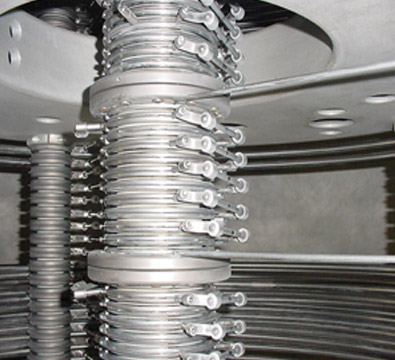
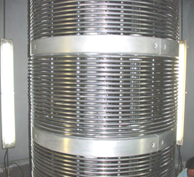
- Resistor based voltage grading system: The accelerator had corona based voltage grading system to define the potential both along with the column support posts and the accelerating tubes. In the corona-based system energy changes, specially for low energy range, were made by shorting the section of accelerator by stainless steel rods to reduce the terminal potential while maintaining the voltage gradient. 3 Giga ohm resistor-based voltage grading system was utilized to replace the pre-existing corona assembly. As a result of this upgradation, voltage stability of the accelerator has improved to 2kV in 15MV terminal potential and no shorting rods used for varying the terminal voltages from 4 MV to 16 MV. After a few years of operation, resistances were falling off the column support posts and a new rigid mounting system utilizing the corona mounting brackets attached to the column support posts has been implemented to avoid the same. In every gap of column support posts, the pair of 3 Giga ohm resistances has been connected by flexible braided connectors, preventing resistance breakage due to excessive vibration.
- Conversion of Double Unit Structure to Single Units: Initial design of accelerator structure consisted of columns arranged in terms of double units with each double unit consisted of six 11 electrode tubes and one shorter 8 electrode tube. On each side of 15 UD accelerator tank there were 7 such double units and one singlet consisting of 3 full-lengths (11 gap tubes) and one 4 gap tube. In case of any tube discharge or tank spark problems, one could pinpoint only the doublet structure. Further during unit-wise conditioning to bring the terminal voltage up one had to condition the machine by 2 units at a time. The configuration of the machine units was reorganized and updated by connecting the center point of each 8 gap tube to a corresponding casting plate through a Galvanized Iron wire solving previous issues. The system has functioned well and single unit conditioning is now possible.
- Installation of Faraday Cup -031: A faraday cup was installed at the exit of the accelerator (outside the tank) to monitor beam current. This configuration helps in improving the transmission of beam current and simplifies beam tuning.

Beam Pulsing System:
The Beam Pulsing system was upgraded by installing a new multi-harmonic buncher. The beam pulsing system has the following features:
- Multi Harmonic Buncher operates with a fundamental frequency of 12.125 MHz and it can use up to 3 harmonics.
- Spiral cavity was installed to avoid phase drift due to variation in flight path of the beam through the accelerator.
- Efficiency of the bunching is 50%
- The time resolution achieved for various beams is 1.2 ns to 2 ns.
- Chopper and TWD may also be used to give repetition rates between 250ns to 4 μs. The Multi-Harmonic Single Gap Buncher, operating at the bunching frequency of 12.125 Mhz and its harmonics, can provide a pulsed beam of more than 50% bunching efficiency. The typical time resolution achieved is between 1 to2 ns.
Stripper:
- The Recirculating gas stripper system:
- A new turbo-molecular pump (TMP)–based recirculating system was designed and installed in the high-voltage terminal of the 15 UD Pelletron for routine operation. Replacing the earlier sublimation pumps, two TMPs now maintain improved vacuum during gas stripper runs, leading to excellent beam transmission. Their backing ports of these TMPs are connected to the stripper gas inlet, allowing gas emerging from the canal to be collected in a large volume, repumped, and recirculated. Differential pumping minimizes gas leakage into the accelerator tubes, while any losses are compensated by controlled fresh gas input. The recirculating gas passes through a hydrocarbon filter to improve purity. This upgrade has significantly enhanced overall beam transmission and enabled delivery of very low-energy beams, which was not feasible with the earlier system.


- Foil strippers: Two types of carbon foils - indigeneously prepared EC (Evaporation Condensation technique) foils at IUAC and LPA (Laser Plasma Ablated) foils procured from Technical University of Munich have been used for stripping in the terminal of 15 UD pelletron accelerator. EC foils due to short lifetime with heavier beams of I, Ag, and Au, are used limitedly while LPA foils with structure composed of randomly oriented nanocrystals ensures longer life time against radiation damage.
- Two new foils stripper assemblies with capacity of 50 foils of 5/8 inch diameter- one each before and after analyzing magnet, have been added for producing higher charge state beam. These are utilized to enhance energy of the ion beam while accelerating through LINAC and also for experiments requiring higher charge states. Two controllers were indigenously developed and installed to control the operation of these foil stripper assemblies.


Chiller:
- A new SF6 chiller replaced the older chiller which was being used inside accelerator tank to regulate the temperature of SF6 gas inside tank at around 25 deg C. This new chiller is installed outside the tank. This is done to avoid any kind of accident which may occur during the operation of accelerator. It is of shell and tube type. Chilled water is circulated in the tube which cools SF6 gas present in the shell. The designed heat load for this chiller is 16,500 kcal/hr. Fabrication of this chiller is done by a local vendor (Air Fridge).
Group members and contact address


Media Gallery
Last Updated: 29 October 2025