

Negative Ion Implanter beam Facility (NIIBF)
The negative ion implanter accelerator facility at IUAC provides highly stable, collimated negative and singly charged ion beams with variable low energies (30–200 keV) and current intensities ranging from a few nA to a few μA. The minimum beam spot size achievable is of 5 mm × 5 mm. However it can vary depending on ion energy and species. This makes the facility an excellent tool for research in material science through ion-solid interactions in the nuclear energy loss regime, such as material synthesis, device fabrication, and material modifications.
Facility Features:
- Room temperature, high vacuum(<5×10⁻⁶ Torr) implants
- Control over beam incident angle for ion implantation
- Precise dose control and possibility of wide range of doses (1011 to 1018ions/cm2)
- Precision area doping with masking
- Predefined depth profile of dopants determined by ion energy
- No energy contaminants
- Implantation free from impurities such as oxygen and hydrogen
- Uniform distribution
- Reproducible
The ion implanter consists of an ion source, accelerating column, mass analyzer, and target chamber. Several components have been indigenously developed at IUAC, including high-voltage platforms, electrostatic quadrupole triplet lenses, electrostatic steerers, and high-vacuum experimental chambers.
Ion Source and Beam Transportation
The ion source in use for generating negative ions is MC-SNICS. The source and its electronic devices are placed on a high voltage platform (200kV) and those are controlled through optical fiber communications. Ion source uses accelerated cesium ions striking a cold cathode to produce a negative ion beam of cathode material, provided the material could form negative ions. A conical-shaped tantalum ionizer immersed in cesium vapor produces cesium positive ions. These positive ions are accelerated towards the negatively biased cathode, which then accelerates negative ions always from the cathode. Not all elements form stable negative ions. Molecular ions are used in those cases by choosing the lightest possible molecule, such as hydrides.
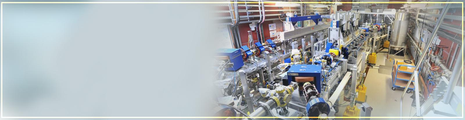
Ion beams extracted from the source are accelerated through three accelerating tubes and mass analyzed by a dipole magnet and injected into the beamline at ninety degrees. The figures show; 1) Implanter facility, 2) Ion source at the high voltage platform and the accelerating column for the acceleration of ions and 3) The dipole magnet which switches the ion beams to the beam line. A target chamber at the end of the beamline has the provision of both linear and rotational movement of the target wafer. Linear movement is controlled by using motorized linear motion feedthrough while rotational movement is done manually.


Available ion species
I. Elemental Ion Beams
| 7Li 100nA |
11B 400nA |
12C 1µA |
16O 1µA |
27Al 130nA |
| 28Si 1µA |
31P 1µA |
32S 200nA |
48Ti 400nA |
56Fe 200nA |
| 58Ni 1µA |
59Co 1µA |
63Cu 1µA |
74Ge 500nA |
107Ag 1µA |
| 197Au 1µA |
II. Molecular Ion Beams
| 24C2 1µA |
49TiH 1µA |
54CrH2 1µA |
40MgO 100 nA |
62CrH 350nA |
62CrH2 1nA |
28Si2 300nA |
27Al2 1nA |
Research Activities
Ion Source Related Developments
Efforts have been made to improve ion current intensities and develop new ion beams as per experimental demands. Mass analysis confirmed that stable cluster beams can be produced, with beam currents varying over several orders of magnitude depending on the element and cluster size. Cluster ion beams of Cₙ⁻, Alₙ⁻, and Siₙ⁻ have been successfully generated. For carbon, clusters up to Cₙ⁻ (n > 11) have been observed, while for aluminium and silicon, clusters up to n = 5 were detected. At larger cluster sizes, mass interferences between different species become evident due to the limited mass resolving power of the analyzing magnet. This study establishes the feasibility of producing and delivering cluster ion beams, thereby expanding the experimental capabilities of the ion implanter facility. Such beams open new avenues for materials science applications, particularly in ion implantation, nanostructuring, and controlled material modification studies.
Material Science Experiments
The facility is primarily used for material science experiments such as material synthesis, device fabrication, and material modifications.
Last Updated: 27 October 2025