
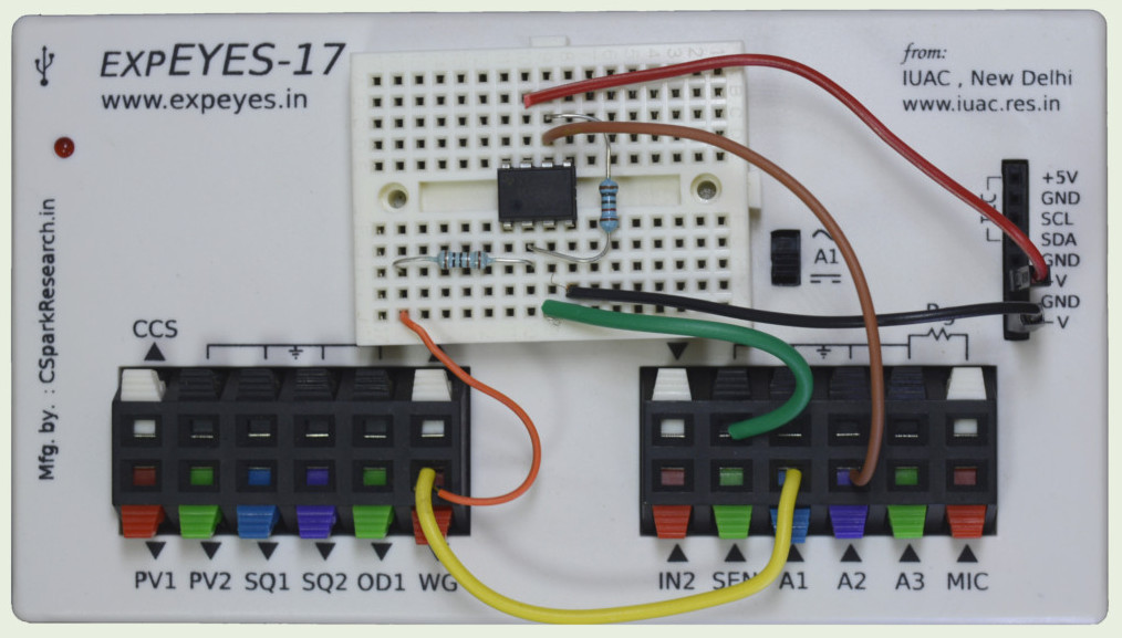
The schematic is wired as shown in the diagram below. Ri = 1k and Rf = 10k. The WG amplitude is set to 80 mV, you may try a 1 volt input to observe the clipping of the the output, since it exceeds the supply voltage of +/- 6 volts.
|
|
| Wiring Diagram | Photograph of the experimental setup. Used OP07 (pin configuration of uA741) |
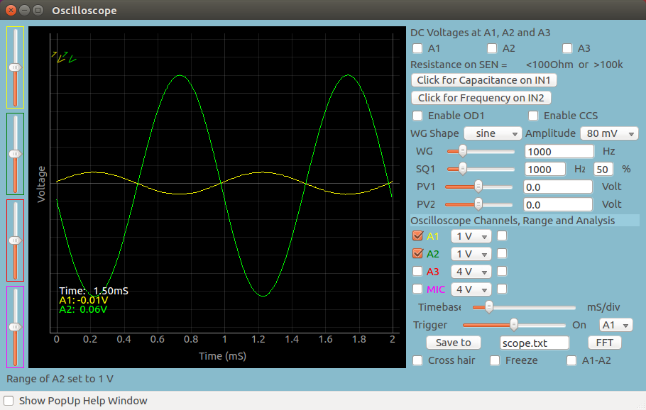 |
| Screen shot of the oscilloscope program showing inputs and output of an Inverting Amplifier. Gain is -10 |
| import eyes17.eyes p = eyes17.eyes.open() from pylab import * p.set_sine(200) p.set_pv1(1.35) # will clip at 1.35 + diode drop t,v, tt,vv = p.capture2(500, 20) # captures A1 and A2 xlabel('Time(mS)') plot([0,10], [0,0], 'black') ylim([-4,4]) plot(t,v,linewidth = 2, color = 'blue') plot(tt, vv, linewidth = 2, color = 'red') show() |
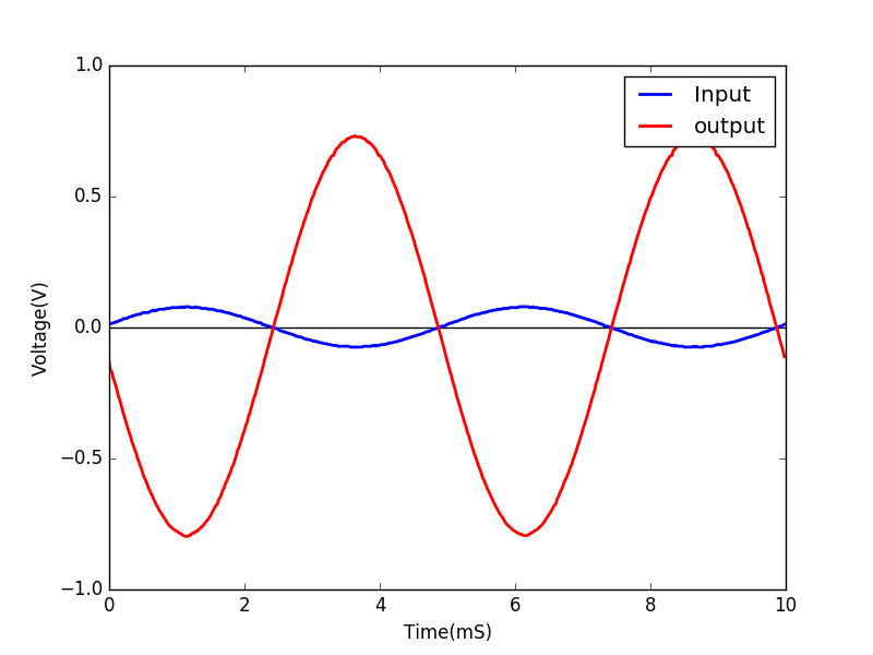 |
| Python program to capture and display A1 and A2 | Output of the code |