
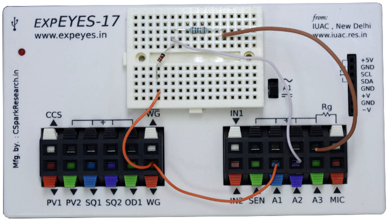
The waveform generator WG is set to give a sine wave of 1kHz. It is monitored by oscilloscope channel A1. The signal after the diode is monitored by A2. The observed waveform will be a bit noisy without the load resistor, connecting a 1k resistor gives a clean rectified waveform. The voltage drop across the diode is clearly visible. Connect different values of capacitors to view the filtering effect.
|
|
| Wiring Diagram | Photograph of the experimental setup |
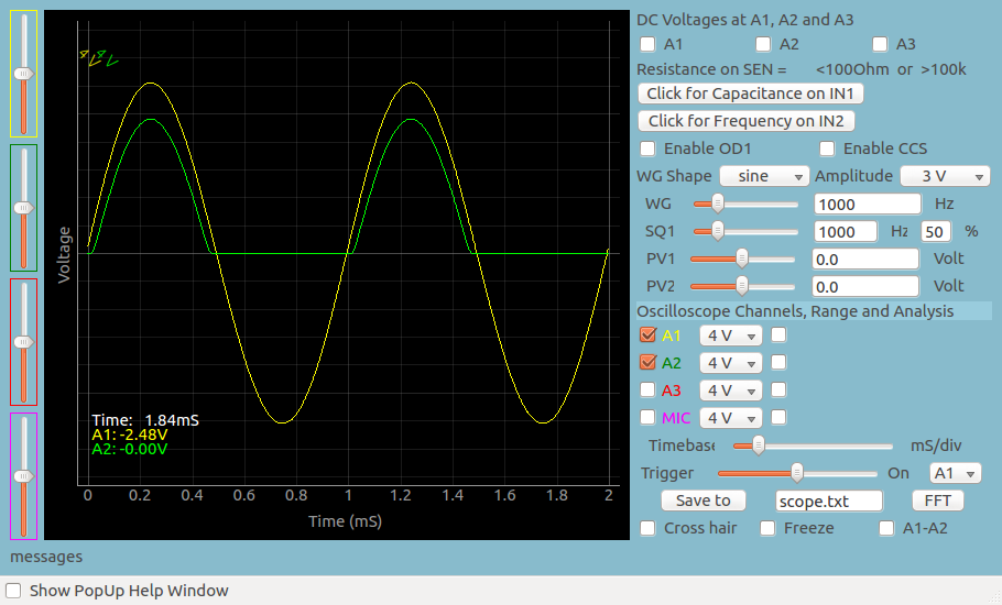 |
| Screen shot of the oscilloscope program showing input and output of half wave rectifier. 1N4148 diode at 1000Hz and 1kOhm load resistor. |
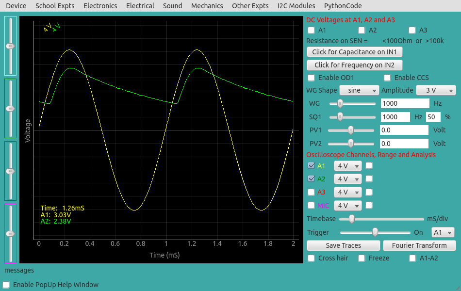
Every diode has a junction capacitance that acts like a capacitance connected in parallel to the ideal PN junction. Junction capacitance of 1N4148 is only 4pF but 1N4007 has a junction capacitance of 20pF. The rectified output, without external load resistor, for 1N4007 is shown below. The 1MOhm input impedance of channel A2 will be always present.
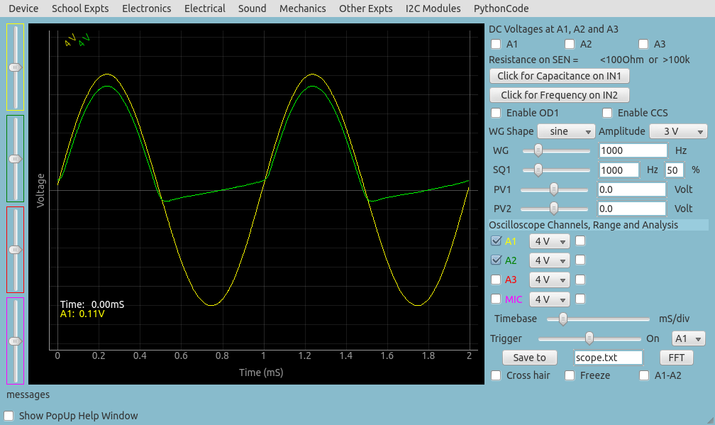
| import eyes17.eyes p = eyes17.eyes.open() from pylab import * p.set_sine(200) t,v, tt,vv = p.capture2(500, 20) # captures A1 and A2 xlabel('Time(mS)') ylabel('Voltage(V)') plot([0,10], [0,0], 'black') ylim([-4,4]) plot(t,v,linewidth = 2, color = 'blue') plot(tt, vv, linewidth = 2, color = 'red') show() |
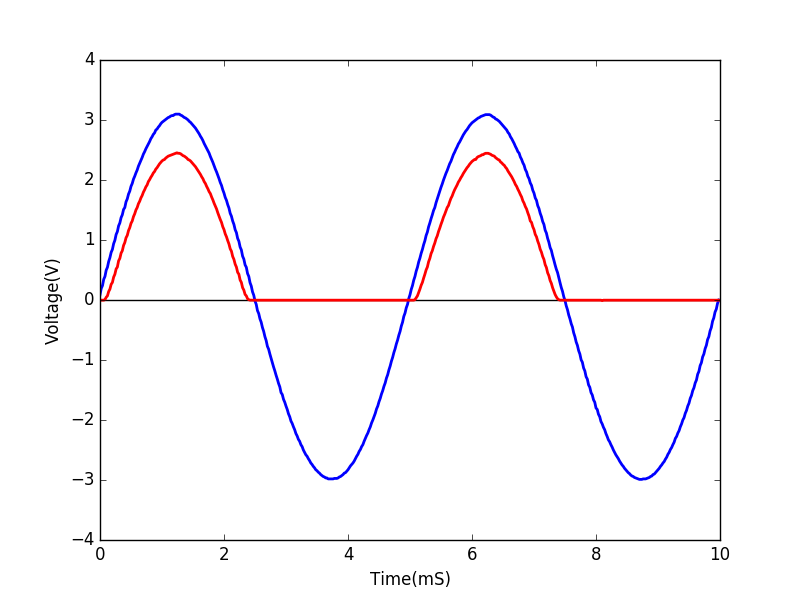 |
| Python program to study half wave rectifier | Output of the code |