A square wave is given to the clock input of the 74LS74 flipflop. The Q-bar
output is connected to the D input. Clear and Preset inputs should be held
HIGH. Every rising edge toggles the output, but nothing happens at the
falling edge.
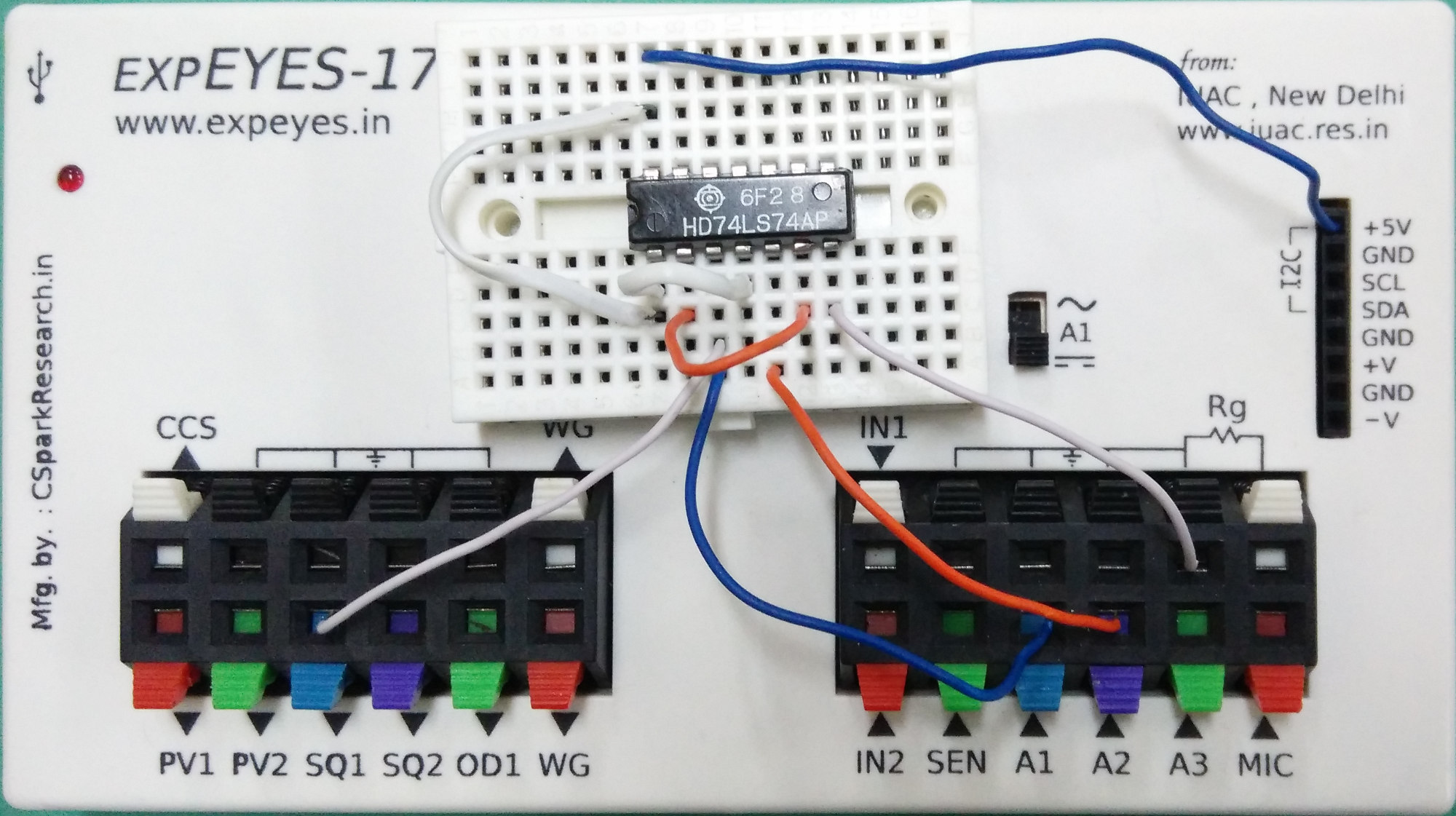
Wiring Diagram
Photograph of the experimental setup.
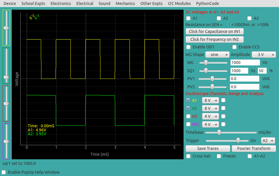
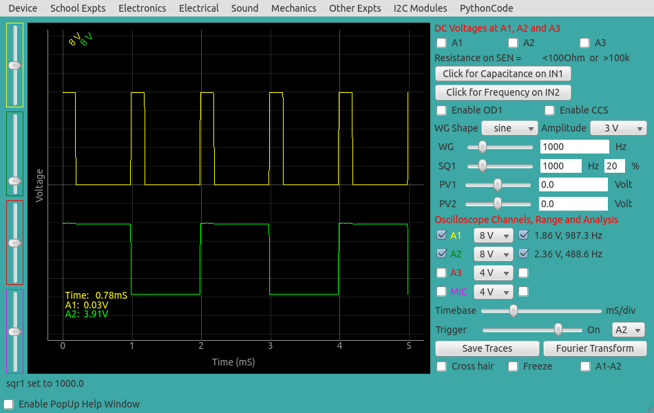
The duty cycle of the output waveform will be 50% irrespective of the duty
cycle of the input waveform, as shown below.