
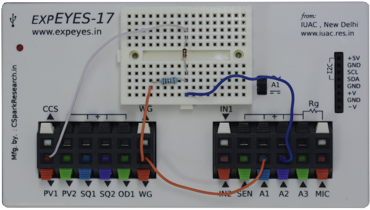
The waveform generator WG is set to give a sine wave of 1kHz. It is monitored by oscilloscope channel A1. The signal after the resistor 10K is monitored by A2.In order to clip the sine wave we are giving DC source from PV1. Since the clipped portion occurs with this circuit in the positive portion of the AC signal, it is the positive amplitude that is clipped.
|
|
| Wiring Diagram | Photograph of the experimental setup |
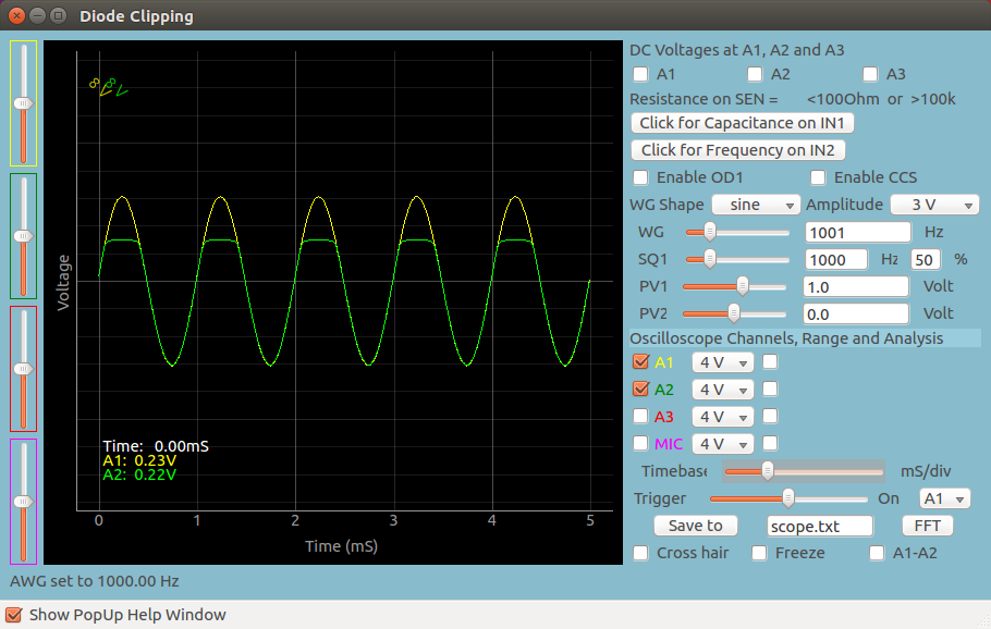 |
| Screen shot of the oscilloscope program showing inputs and output of Positive Diode Clipping. 1N4148 diode at 1000Hz and 1kOhm load resistor. |
| import eyes17.eyes p = eyes17.eyes.open() from pylab import * p.set_sine(200) p.set_pv1(1.35) # will clip at 1.35 + diode drop t,v, tt,vv = p.capture2(500, 20) # captures A1 and A2 xlabel('Time(mS)') plot([0,10], [0,0], 'black') ylim([-4,4]) plot(t,v,linewidth = 2, color = 'blue') plot(tt, vv, linewidth = 2, color = 'red') show() |
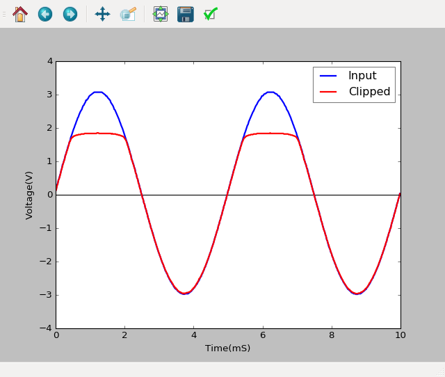 |
| Python program to Diode Clipping | Output of the code |