Transient response of RL circuit
A voltage step is applied to a series RL circuit and the resulting voltage
variation across the capacitor is captured and analyzed.

|
|
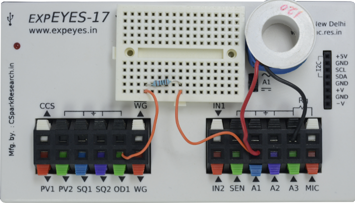
| Wiring Diagram |
Photograph of the experimental setup. |
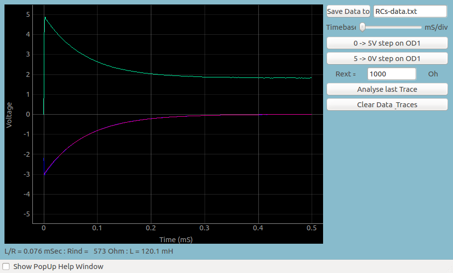
The voltage steps are generated on OD1 by
clicking on the buttons on the GUI. The observed waveforms are shown
below, showing the voltage variation across the inductor in each case. It
can be observed that when a 5 to 0 volt step is applied, the polarity of
the voltage across the inductor is reversed and the voltage goes to
negative immediately. After that the voltage reduces exponentially,
driving a current through the resistor. The resulting wave form is fitted
with V = Vo x exp(R/L * t) to extract the R/L value. The value of inductor
is calculated from that.
|
| Screen shot of the voltage across an inductor. |